6 pump/lift/mast, 6 pump/lift/mast -5, Lift system -5 – JLG 1230ES Service Manual User Manual
Page 35
SECTION 3 - THEORY OF OPERATION - 1230ES
3121222
– JLG Lift –
3-5
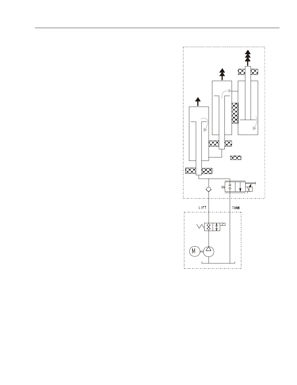
3.6 PUMP/LIFT/MAST
An electrically driven hydraulic pump provides hydraulic
pressure to actuate the steering and lift up. Lift down is
"powered" by gravity. The lift actuator is a three stage
hydraulic cylinder. The cylinder pistons are not sealed so
fluid can flow from one cylinder to the next. The area of the
piston that fluid touches on both sides does not provide
lift because the forces on both sides cancel each other.
The area of the piston with the rod behind it provides the
lifting force necessary because no pressure is there to
cancel the force applied by the pressure on the other side.
To lift the platform, the solenoid energizes and opens the
lift up valve. The pump speed is set proportional to joy-
stick position. Fluid flows into the first cylinder, through the
hollow rod. This extends the barrel of the first cylinder. The
rod to the second cylinder is attached to the barrel of the
first cylinder. Fluid is passed by a port in the first cylinder
to the hollow rod of the second cylinder. That extends the
second cylinder. The barrel of the second cylinder is
attached to the barrel of the third cylinder. A port in the
barrel of the second cylinder passes fluid to the third cylin-
der. This extends the third cylinder, and lifts the platform.
To bring down the platform, the lift down valve opens, pro-
portional to joystick position, and allows fluid out of the
cylinder, allowing it to retract by gravity.
Figure 3-4. LIFT SYSTEM
The Power Module is essentially a "low-side" switch for the
pump motor. The positive terminal of the pump is tied to
Battery Positive after the Line Contactor. The negative ter-
minal of the pump connects to the P Terminal of the Power
Module, which switches current through MOSFET transis-
tors to the Battery Negative.
For variable speed pump operation, the MOSFET transis-
tors switch On and Off at high frequencies (16kHz). The
Duty Cycle is varied to control the voltage applied to the
pump motor. When the MOSFET's spend 50% of the
period On and 50% Off, approximately ½ of the available
Battery power will be applied to the pump motor. Similarly,
the MOSFET are On continuously (100% Duty Cycle) to
PLATFORM
ATTACHMENT
CHASSIS