Personalities, Interlocks, Personalities -4 interlocks -4 – JLG 1230ES Service Manual User Manual
Page 34
SECTION 3 - THEORY OF OPERATION - 1230ES
3-4
– JLG Lift –
3121222
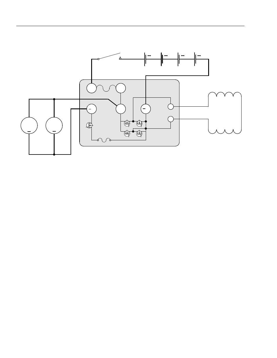
The Field Windings also provide direction reversal for trac-
tion. When driving forward, MOSFET switches 1 and 4
turn On to apply positive potential to F2 and ground
potential to F1. In reverse, MOSFET switches 2 and 3 turn
On to apply positive potential to F1 and ground potential
to F2. Theses switches are pulse-width modulated by the
Power Module to maintain a fixed relationship between
Field and Armature Current.
Two electrically-released parking brakes are mounted to
the rear of the drive motors. The Ground Module ener-
gizes the two 24V electro-magnets when appropriate to
allow vehicle motion. The parking brakes can be released
electrically for emergency vehicle towing.
Personalities
Traction system Personality settings can be changed via
ANALYZER -> PERSONALITIES -> DRIVE:
• ACCEL - Time to ramp from 0% to 100% of command
• DECEL - Time to ramp from 0% to 100% of command
• MINIMUM - Minimum drive speed (Creep)
• MAXIMUM - Maximum drive speed when platform is
stowed
• ELEV. MAX - Maximum drive speed when platform is
elevated
Interlocks
As the machine travels down an incline the drive power
output will be reduced proportionally to avoid overspeed-
ing the vehicle. A bad tilt sensor will force the control sys-
tem to assume maximum incline and reduce drive power
accordingly.
Creep mode (reduced drive speed) will be active if the
control system determines the platform is elevated. Drive
may be prevented by a different interlock, however.
Drive will be prevented if any of the following occur:
• Vehicle is tilted, elevated and ANALYZER -> MACHINE
SETUP -> TILT CUTOUT is set to YES.
• Batteries are being charged (0V is applied to ground
board J1-29)
• Vehicle is elevated above the calibrated Drive Cutout
height and ANALYZER -> MACHINE SETUP -> DRIVE
CUTOUT is set to YES.
Figure 3-3. Drive Motors Schematic - 1001092456 (ZAPI) Power Module
+
24V
+
+
+
Line Contactor
Right Field Winding
Left Field Winding
Power Module
Left
Armature
Right
Armature
+
+
BF1
BF2
B
+B
T
F1
F2
Field
MOSFETS
Armature
MOSFET
Shunt