3 calibration instructions, Calibration instructions -4 – JLG 1100S Service Manual User Manual
Page 278
SECTION 6 - JLG CONTROL SYSTEM
6-4
– JLG Lift –
3121256
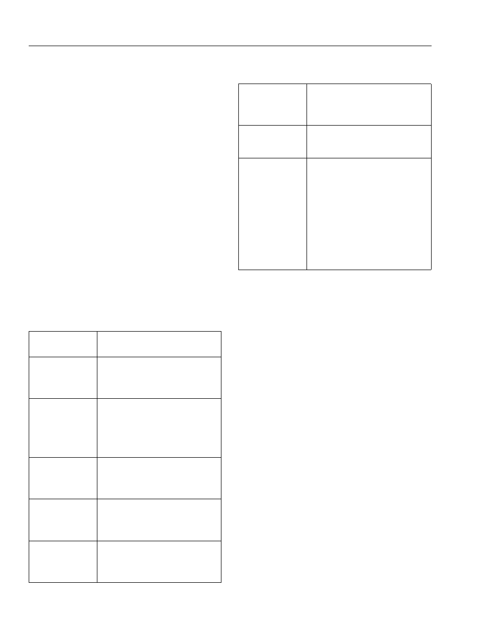
6.3 CALIBRATION INSTRUCTIONS
This machine incorporates a variety of sensors and a high
degree of function interaction. For safety and proper
machine functionality, the calibration procedures must be
repeated for any control module replacement, system cal-
ibration related fault, or removal or replacement of any
sensors, valves, coils, motors, or pumps. The chart below
lists the calibrations required and potential reasons for re-
calibration. All calibration procedures are menu driven
through the use of the standard analyzer. With the excep-
tion of steering calibration, no external tools are required
to complete the calibration procedures. The user is
prompted to exercise the machine in a specific order to
use the machines physical properties to consistently
establish sensor response and the interaction of valves,
pumps, and motors. Steering calibration also uses the
analyzer and is performed on one side of the machine at a
time requiring the use of a string or other means to deter-
mine when the tires are in line with each other. With the
exception of the load control calibration, all calibrations
are accessed by connecting the analyzer into the control
system inside the main terminal box or on the bottom of
the platform control box.
Table 6-1. Calibration Instructions
Calibration
Procedure
Reasons for Re-calibration
Steering Calibration
Ground module replacement
Chassis module replacement
Steer sensor removal or replacement
Persistent wheel misalignment
Drive Calibration
Ground module replacement
BLAM module replacement
Drive pump/coil replacement
Drive pulls to one side
Drive lugs engine
Poor slow speed control
Platform Leveling
Calibration
Ground module replacement
Platform module replacement
Platform level sensor removal or replacement
Platform level sensor calibration fault
Platform Level Crack
Point Calibration
Platform module replacement
Ground module replacement
Platform level valve/coil replacement
Erratic platform leveling
Lift Crack Point
Calibration
Ground module replacement
Lift proportional valve/coil replacement
Erratic controlled arc operation
Erratic controlled boom angle operation
Telescope Crack Point
Calibration
Ground module replacement
Telescope proportional valve replacement
Erratic controlled arc operation
Erratic controlled boom angle operation
Chassis Tilt
Calibration
Ground module removal or replacement
Main terminal box removal or replacement
Tilt indication inaccuracy
Boom Sensors
Calibration
Ground module removal or replacement
BLAM module removal or replacement
Boom angle sensor removal or replacement
Boom length sensor removal or replacement
Moment pin removal or replacement
Boom angle sensor calibration fault
Boom length sensor calibration fault
Moment pin fault
Failed BCS functional check
Boom control system inaccuracies
Installing or removing approved accessories
Changing Platform Size
Table 6-1. Calibration Instructions