JLG 1100S Service Manual User Manual
Page 109
SECTION 3 - CHASSIS & TURNTABLE
3121256
– JLG Lift –
3-67
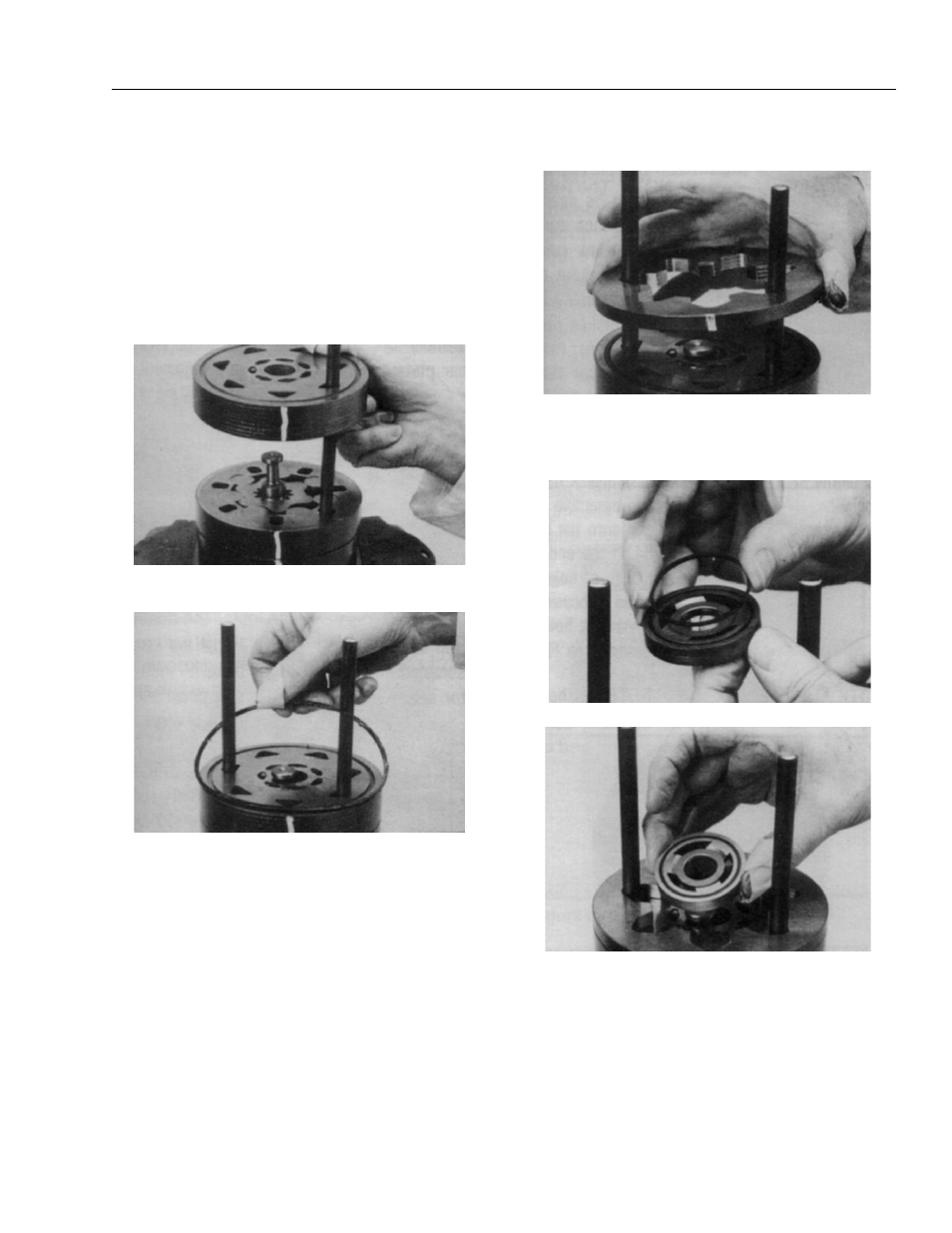
NOTE: The manifold (7) is made up of several plates
bonded together permanently to form an integral
component.The manifold surface that must contact
the rotor set has it’s series of irregular shaped cavi-
ties on the largest circumference or circle around the
inside diameter.The polished impression left on the
manifold by the rotor set is another indication of
which surface must contact the rotor set.
15. Assemble the manifold (7) over the alignment studs
and drive link (10) and onto the rotor set. Be sure the
correct manifold surface is against the rotor set.
16. Apply grease to a new seal ring (4) and insert it in
the seal ring groove exposed on the manifold.
17. Assemble the commutator ring (6) over alignment
studs onto the manifold.
18. Assemble a new seal ring (3) flat side up, into com-
mutator (5) and assemble commutator over the end
of drive link (10) onto manifold (7) with seal ring side
up.
19. If shuttle valve components items #21, were
removed from the end cover (2) turn a plug (21),
loosely into one end of the valve cavity in the end
cover. A 3/16 inch Allen wrench is required.