5 frame sway and attachment tilt levers, Frame sway and attachment tilt levers – JLG 534D-10 User Manual
Page 80
Cab and Covers
4.6
534D-9, 534D-10 & 544D
2. Install the bolts securing the boom joystick to the
cab.
3. Connect the battery negative (-) cable to the battery
negative (-) terminal.
4. Test the boom extend/retract and boom lift/lower
joystick function:
a. Move the joystick handle rearward, activating the
boom lift function. The boom should RISE.
b. Move the joystick handle forward, activating the
boom lower function. The boom should LOWER.
c. Move the joystick handle to the right, activating
the boom extend function. The boom should
EXTEND.
d. Move the joystick handle to the left, activating the
boom retract function. The boom should
RETRACT.
e. Depress the left side of the switch (optional) to
activate the tilt up function. The attachment
should TILT UP.
f. Depress the right side of the switch (optional) to
activate the tilt down function. The attachment
should TILT DOWN.
5. Close and secure engine cover.
4.3.5
Frame Sway and Attachment Tilt
Levers
a. Lever Removal
1. Park the machine on a firm, level surface, level the
machine, fully retract the boom, lower the boom,
place the travel select lever in the (N) NEUTRAL
position, engage the parking brake and turn the
engine OFF.
2. Place a Do Not Operate Tag on both the ignition key
switch and steering wheel, stating that the machine
should not be operated.
3. Disconnect the battery negative (-) cable at the
battery negative (-) terminal.
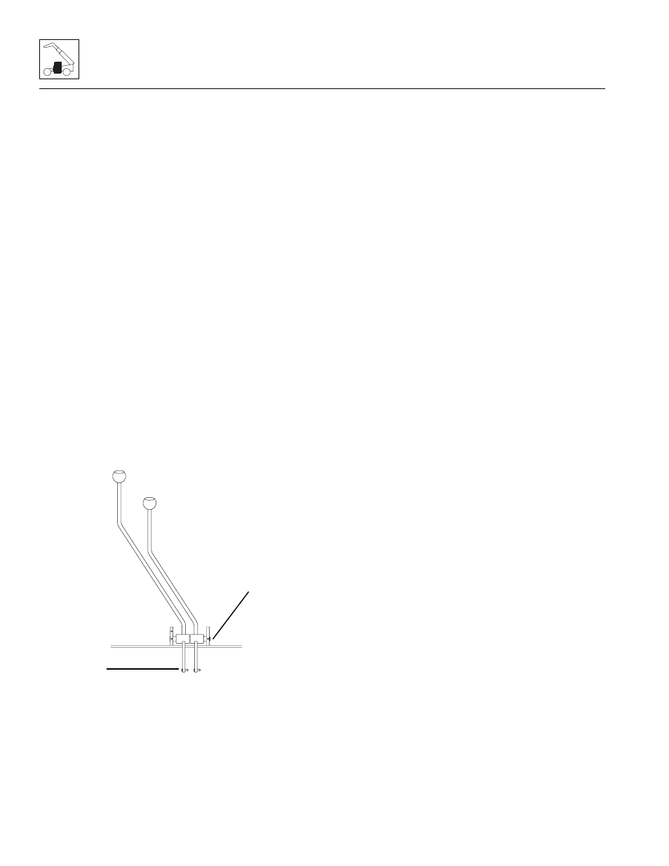
4. Disconnect the link (4) between the lever and the
main control valve.
5. Remove the cotterpins and pull the shaft (5) out of
the lever mounting brackets. Note the location of the
spacers between the levers.
6. Remove the lever from the cab.
b. Lever Installation
1. Install the lever at the mounting bracket on the cab
floor.
2. Install the shaft, spacers and cotter pins.
3. Install the link between the lever and the main
control valve.
4. Install the lever knob.
5. Connect the battery negative (-) cable to the battery
negative (-) terminal.
6. Test the lever functions:
Frame Sway and Attachment Tilt Levers
a. Move the lever rearward, activating the
attachment up function. The attachment should
TILT UP.
b. Move the lever forward, activating the attachment
down function. The attachment should TILT
DOWN.
c. Move the Tilt lever rearward, activating the right
frame sway function. The frame should SWAY to
the RIGHT.
d. Move the Tilt lever forward, activating the left
frame sway function. The frame should SWAY to
the LEFT.
4.3.6
Left Hand Tilt and/or Left Hand Tilt/
Sway Lever (If Equipped)
a. Lever Removal
1. Park the machine on a firm, level surface, level the
machine, fully retract the boom, lower the boom,
place the travel select lever in the (N) NEUTRAL
position, engage the parking brake and turn the
engine OFF.
2. Place a Do Not Operate Tag on both the ignition key
switch and steering wheel, stating that the machine
should not be operated.
MX0810
4
5