2 air cleaner assembly installation, 12 engine replacement, 1 engine removal – JLG 534D-10 User Manual
Page 120: Engine troubleshooting, Air cleaner assembly installation, Engine replacement, Engine removal
Engine
7.12
534D-9, 534D-10 & 544D
7.11.2
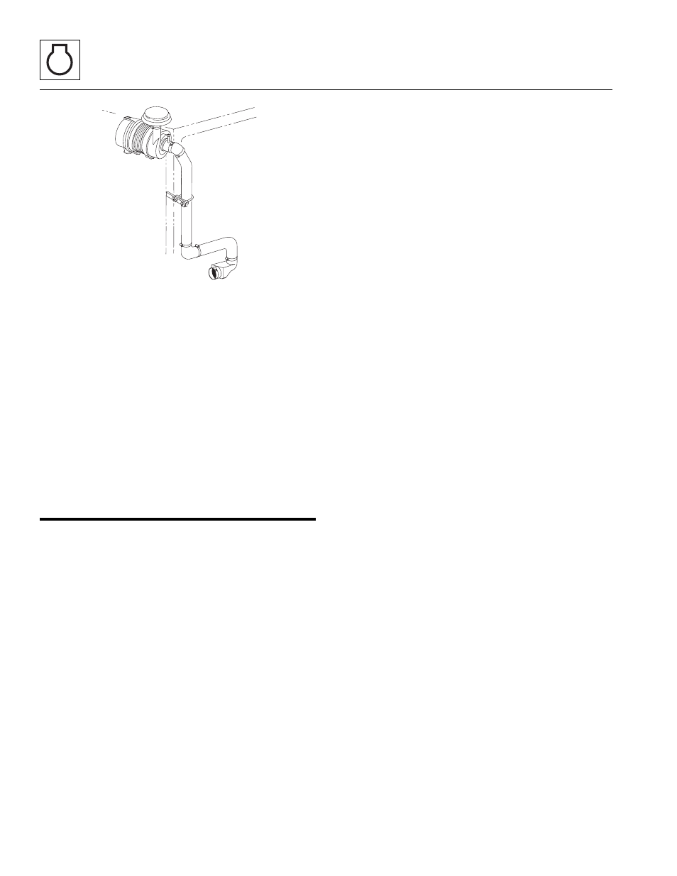
Air Cleaner Assembly Installation
Note: Apply Loctite
®
242 threadlock to the capscrew
threads before installation.
1. With the air cleaner assembly attached, install the air
cleaner mounting bracket using capscrews and nuts.
2. Place the loosened clamps over the air outlet elbow
and install elbow on the air cleaner assembly.
3. Adjust and tighten both clamps before starting the
machine.
4. Connect the battery negative (-) cable to the battery
negative (-) terminal.
5. Close and secure the engine cover.
7.12
ENGINE REPLACEMENT
7.12.1
Engine Removal
Note: The radiator and oil cooler must be removed from
the machine before engine removal. Refer to
7.7, “Cooling System.” Several additional components
must be removed before engine removal. They will be
addressed in the following procedures.
Note: The hydrostatic drive pump can be left in place
with the engine or separated from the engine before
engine removal. See Section 6.5.1, “Drive Pump
Removal.”.
1. Level the machine, ground the attachment, place the
travel select lever in NEUTRAL (N), engage the
parking brake and shut off the engine.
2. Place a Do Not Operate Tag on both the ignition key
switch and the steering wheel, stating that the
machine should not be operated.
3. Open the engine cover. Allow the system fluids to
cool.
4. Remove the battery negative (-) cable from the
battery negative (-) terminal.
5. Remove the engine cover, rear cover and the engine
dust shield.
6. Place a funnel at the base of the radiator to channel
the drained coolant into the container. Loosen the
drain plug and slowly remove to allow the coolant to
drain. Transfer the coolant into a properly labeled
container. Dispose of properly if coolant needs to be
replaced. Replace the radiator drain plug.
7. Loosen and remove both charge air tubes from the
charge air cooler (544D w/ John Deere engine and
all Cummins engines).
8. Loosen the radiator hose clamps at the engine.
Work the hose off the engine. Position the hose out
of the way to allow radiator removal. Inspect the
hose, and replace if necessary.
Note: Disregard the following directions in step 10 and
11 if pump is being left on machine and continue to
step 12.
9. Drain the hydraulic oil reservoir or install a vacuum at
the hydraulic oil reservoir filler neck.
10. Disconnect and plug the hydraulic oil cooler hoses
and cap the fittings on the oil cooler.
11. Unplug the wire harness at the hydrostatic drive
pump. Disconnect, label and plug the hoses on the
hydrostatic drive pump if pump is being removed
with the engine.
12. Loosen and remove the twelve bolts holding the
pump mounting plate to the engine bellhousing.
13. Loosen and remove the mounting bolts and nuts
holding the radiator/cooler to the frame.
14. Attach a suitable strap to the radiator/cooler
assembly and carefully remove.
15. Loosen the clamps on each heater hose on the
engine. Plug the heater hoses if necessary.
Note: The engine harness is routed and attached to the
engine using hold-down clamps and plastic wire ties at
various places on the engine. Before removing engine,
ensure that the harness has been completely separated
(disconnected) from the engine. Move the harness clear
of the engine, and with the help of an observer, ensure
that engine clears the harness during removal.
16. Label and disconnect all wire harness connections on
the engine.
17. Disconnect the fuel lines at the engine. Install a plug
in the end of fuel inlet and return line.
MX0970