13 engine drive plate/coupling, 1 drive plate/coupling removal, 2 drive plate/coupling installation – JLG 534D-10 User Manual
Page 122: Section 8, Engine drive plate/coupling, Drive plate/coupling removal, Drive plate/coupling installation
Engine
7.14
534D-9, 534D-10 & 544D
22. If installing new hydraulic oil filters, fill with Mobilfluid
424
®
Tractor Hydraulic Fluid (ISO 46) before
installing on the filter head.
23. Check that all hydraulic system, electrical system,
cooling system, fuel system, and exhaust system
connections are correct and connected tightly
Note: Have an assistant stand by with a Class B fire
extinguisher. Start and idle the engine.
24. Run engine to normal operating temperature then shut
off the engine. While the engine is cooling, check for
leaks.
25. Allow the engine to cool. Check the radiator coolant
level, and top off with a 50/50 mixture of ethylene
glycol and water. Replace the radiator cap.
26. Check for leaks from the engine, main hydraulic pump
and lines, drive pump, hydraulic reservoir and fuel
tank. Check the levels of all fluids and lubricants. Fill
as required.
Note: During the full throttle check:
• DO NOT operate any hydraulic function.
• DO NOT steer or apply any pressure to the steer-
ing wheel.
• Keep the transmission in NEUTRAL (N).
27. Purge the hydraulic system of air by operating all
boom functions through their entire range of motion
several times. Check the hydraulic oil level.
28. Check for proper operation of all components.
29. Turn the engine OFF.
7.13
ENGINE DRIVE PLATE/COUPLING
7.13.1
Drive Plate/Coupling Removal
1. Level the machine, ground the attachment, place the
travel select lever in NEUTRAL (N), engage the
parking brake and shut off the engine.
2. Place a Do Not Operate Tag on both the ignition key
switch and the steering wheel, stating that the
machine should not be operated.
Note: In order to remove the engine drive plates, the
engine and transmission must be separated.
3. Refer to Section 6.5.1, “Drive Pump Removal,” or
Section 7.12.1, “Engine Removal.”
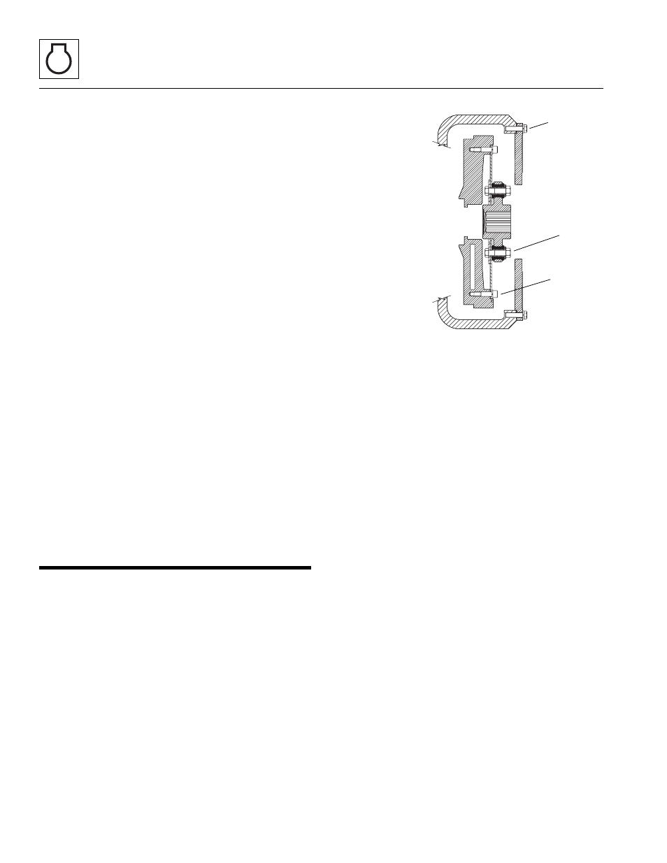
4. Loosen and remove the bolts (1) holding the pump
mounting plate to the engine bell housing. Remove
the mounting plate.
5. Remove the bolts (2) holding the drive plate to the
flywheel.
6. With the drive plates removed, loosen and remove
the bolts (3) holding the coupling to the drive plate.
7. Replace the drive plate and/or the coupler if
damaged.
7.13.2
Drive Plate/Coupling Installation
1. Install the new coupler (3) on the drive plate and
torque the bolts with lock washers to 40-45 lb-ft
(54-61 Nm).
2. Mount the drive plate/coupler assembly (2) to the
flywheel, install the bolts and torque to 40-45 lb-ft
(54-61 Nm).
3. Install the pump mounting plate (1) to the engine bell
housing and torque the bolts to 40-45 lb-ft
(54-61 Nm).
4. Refer to Section 6.5.3, “Drive Pump Installation,”or
Section 7.12.3, “Engine Installation,” for the
remainder of the installation.
MX1000
1
2
3