16 quick switch assembly, 1 disconnecting from an attachment, 2 connecting to an attachment – JLG 534D-10 User Manual
Page 70: 3 quick switch removal, 4 quick switch installation, Quick switch assembly, Disconnecting from an attachment, Connecting to an attachment, Quick switch removal, Quick switch installation
Boom
3.42
534D-9, 534D-10 & 544D
3.16
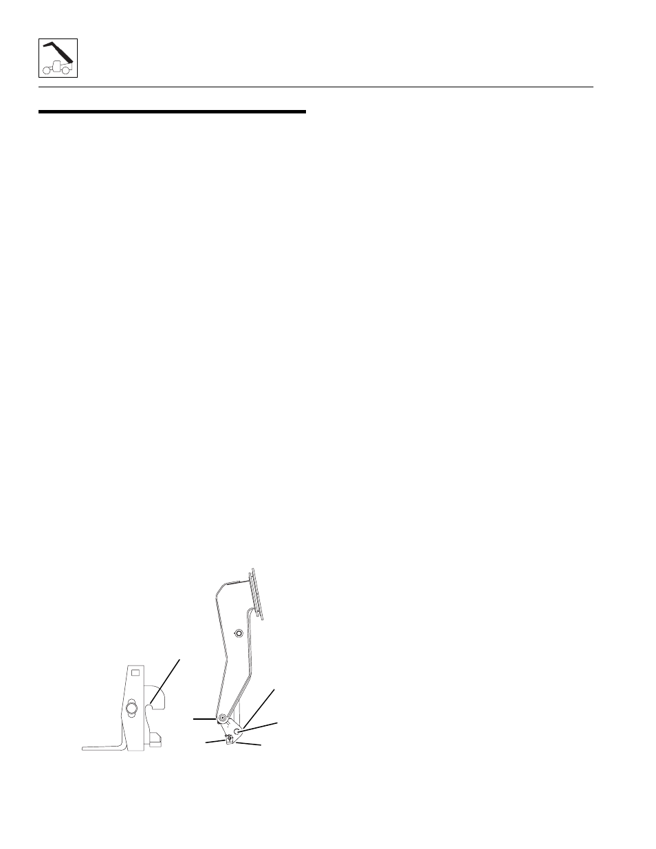
QUICK SWITCH ASSEMBLY
This machine is equipped with a quick switch assembly
system for easy attachment changes.
3.16.1
Disconnecting from an Attachment
1. Park the machine on a hard, level surface.
2. Place the transmission control lever in the (N)
NEUTRAL position and engage the parking brake
switch
3. Level the boom and extend it out approximately
10 ft (3,05 m) and tilt the carriage backward.
4. Exit the machine using both hand holds.
Note: If removing a standard carriage with forks, spread
the forks apart on the carriage shaft. This will help give
the carriage better support to stand alone.
5. If equipped, label, disconnect the auxiliary electric
harness.
6. If equipped, label, disconnect and cap the auxiliary
hydraulic hoses.
7. If equipped, release the swing attachment saddles.
8. Remove the quick switch pin lock pin (1) and pull out
the retaining pin (2) at the bottom of the quick switch
assembly.
9. Return to the operator’s compartment, fasten the
seat belt and lower the attachment to the ground in a
level position. Tilt the attachment forward. This will
rotate the quick switch link back away from the
attachment.
10. Lower and then retract the boom until the
attachment pivot pins have disconnected from the
attachment.
3.16.2
Connecting to an Attachment
1. Retract quick switch to provide clearance. Check to
be sure lock pin (1) is secured in out position with
retainer pin.
2. Align attachment pivot pin with recess in
attachment (3). Raise boom slightly to engage
attachment pivot pin in recess.
3. Engage the quick switch (4).
4. Shut off engine. Exit cab and remove the lock pin (2)
and the slide retainer pin (1) in fully. Secure the
retainer pin in locked position using lock pin.
5. If equipped, swing attachment saddles down and pin
in place.
6. If equipped, uncap and reconnect auxiliary hydraulic
hoses.
7. If equipped, connect auxiliary electric harness.
3.16.3
Quick Switch Removal
1. Remove the lock bolt holding the tilt cylinder rod end
pin to the quick switch assembly. Remove the Tilt
Cylinder pin (5).
2. Support the quick switch assembly.Remove the
capscrew and locknut securing the head pin (6) to
the boom head.
3. Inspect the above pins for nicks or surface corrosion.
Use fine emery cloth to fix minor nicks or corrosion.
If damaged or if it cannot be repaired the pin must be
replaced.
3.16.4
Quick Switch Installation
1. Assemble the quick switch to the boom head. Line
up the quick switch between the mounts on the
boom head. The quick switch should be centered in
the boom head.
2. Coat the quick switch head pin with an anti-seize
compound. Insert the quick switch head pin (6)
through the quick switch and boom head. Secure
with the previous capscrew and locknut.
3. Align the quick switch with the tilt cylinder rod end
and insert the tilt cylinder pin (5). Align the tilt
cylinder pin and screw in the locking bolt. Torque as
required.
MX0550
1
2
3
4
5
6