6 extend cable installation, Extend cable installation – JLG 534D-10 User Manual
Page 43
3.15
534D-9, 534D-10 & 544D
Boom
1. Remove any attachment from the quick switch
assembly. Refer to Section 3.16.1, “Disconnecting
from an Attachment.”
2. Park the machine on a hard, level surface, fully
retract the boom, level the boom assembly, place the
transmission control lever in (N) NEUTRAL, engage
the park brake and shut the engine OFF.
3. Place a Do Not Operate Tag on both the ignition key
switch and the steering wheel, stating that the
machine should not be operated.
4. Open the engine cover. Allow the system fluids to
cool.
5. Remove the battery negative (-) cable from the
battery negative (-) terminal.
6. Remove the hose guards (3) from the rear of the first
boom section.
7. Label, disconnect and cap the extend/retract
cylinder hoses (4). Cap all fittings and openings to
keep dirt and debris from entering the hydraulic
system.
8. Remove the extend/retract cylinder mounting pins
(5) from the strong back/cylinder bracket.
9. Remove the extend cable lock nuts, washers and
springs (6) from the strong back/cylinder bracket.
10. Pull the cable free of the strong back/cylinder
bracket. Fasten a rope to the cable end to aid in
reinstallation.
11. Remove the strong back/cylinder bracket mounting
bolts and remove the strong back bracket (7) from
the machine. Label and tag each set of shims being
removed from above and below the strong back.
12. Remove the push beam mounting bolts. Pull the
push beam extend cable sheave bracket free of the
third boom section.
13. Remove all the extend cable sheave bracket
components from the front of the push beam.
14. Pull the extend cable through the push beam extend
cable sheave bracket.
3.5.6
Extend Cable Installation
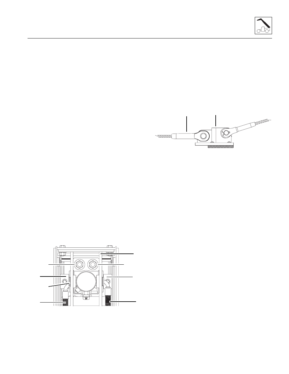
1. Tie a rope to the extend cable threaded end and pull
the cable to the anchor bracket weldment area.
2. Install the extend cable socket end (8) and the
mounting hardware to the extend cable anchor
bracket weldment (9).
3. Assemble all the extend cable sheave bracket
components to the front of the push beam.
Note: The extend cable threaded end must be inserted
through the sheave bracket before the sheave
components are installed.
4. Install the push beam fully into the second boom
section.
5. Install the push beam mounting hardware and the tilt
and auxiliary circuit hose guards at the rear of the
first boom section.
6. Place the strong back in place at the rear of the first
boom section and install the extend/retract cylinder
mounting pin, spacers and retaining clips.
7. Install the previously removed shims to the top and
bottom of the strong back/cylinder bracket.
8. Install and torque the strong back mounting bolts.
9. Uncap and reconnect the previously labeled
hydraulic hoses to the appropriate locations
10. Install the extend cables, springs, washers and lock
nuts into the strong back.
Note: Be certain that the extend cables are stress free
and not twisted.
11. Remove the rope and install the extend cable
springs, washers and lock nuts into the strong back.
12. Tighten the extend cables adjusting nuts (10) until
the gap between the cable flat washer and the
strong back (11) is 1/32 to 1/16 in
(0,79 mm - 1,57 mm). The gap for both washers
should be equal.
MX0260
3
3
4
4
5
6
6
7
MX0270
8
9