2 service brake valve, Service brake valve – JLG 534D-10 User Manual
Page 143
8.19
534D-9, 534D-10 & 544D
Hydraulic System
f.
Main Control Valve Installation
1. Install the main control valve onto the frame, aligning
the bolts with the holes in the end sections of the
main control valve. Slide the main control valve into
position, and tighten the bolts.
2. Prime the main control valve by filling the inlet
openings with fresh, filtered hydraulic oil from a
clean container, before attaching the hoses.
3. Use new oiled o-rings as required. Uncap and
connect all previously labeled hoses, clamps, etc. to
the main control valve.
4. Check the routing of all hoses, wiring and tubing for
sharp bends or interference with any rotating
members, and install tie wraps and/or protective
conduit as required. Tighten all tube and hose
clamps.
5. Start the engine and run at approximately one-third
to one-half throttle for about one minute without
moving the machine or operating any hydraulic
functions.
6. Inspect for leaks and check the level of the hydraulic
fluid in the reservoir. Shut the engine OFF.
Note: Check for leaks and repair as required before
continuing. Add hydraulic fluid to the reservoir as needed.
7. Wipe up any hydraulic fluid spillage in, on, near and
around the machine, work area and tools.
8. Close and secure the engine cover and the hydraulic
oil reservoir/fuel tank cover.
g. Main Control Valve Test
Conduct a pressure check of the hydraulic system in its
entirety. Adjust pressure(s) as required. Refer to Section
8.3.1, “Pressure Checks and Adjustments.”
8.8.2
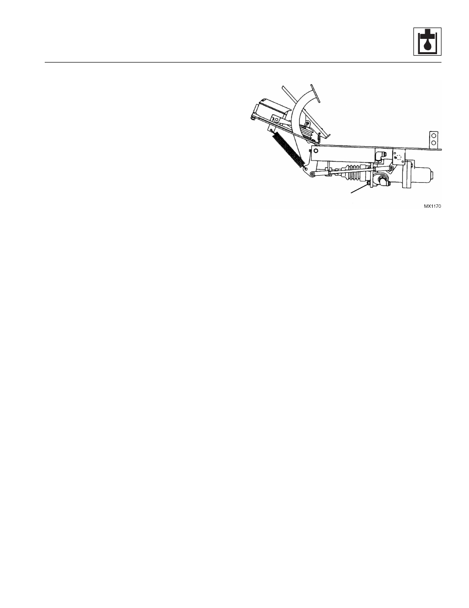
Service Brake Valve
a. Service Brake Valve Removal
1. Park the machine on a firm, level surface, level the
machine, fully retract the boom, lower the boom,
place the transmission control lever in (N) NEUTRAL,
engage the park brake and shut the engine OFF.
2. Place a Do Not Operate Tag on both the ignition key
switch and the steering wheel, stating that the
machine should not be operated.
3. Open the engine cover and the hydraulic oil reservoir/
fuel tank cover. Allow the system fluids to cool.
4. Disconnect the battery negative (-) cable from the
battery negative (-) terminal.
5. Remove belly pan from under cab.
6. Label, disconnect and cap all hose attached to the
service brake valve. Cap all fittings and openings to
keep dirt and debris from entering the hydraulic
system.
7. Remove the four capscrews, four nuts and four
lockwashers (1) mounting the service brake valve to
the service brake bracket.
Note: DO NOT disassemble the service brake valve.
The service brake valve is not serviceable and must be
replaced in its entirety, if defective.
1