2 assembling the hydraulic sub- assembly, 3 hydraulic sub-assembly installation, Assembling the hydraulic sub-assembly – JLG 534D-10 User Manual
Page 67: Hydraulic sub-assembly installation
3.39
534D-9, 534D-10 & 544D
Boom
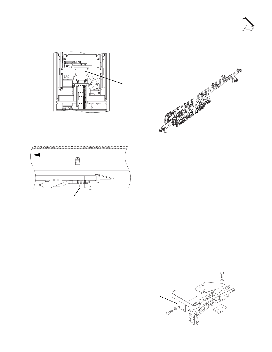
11. Loosen and remove the sub-assembly bracket (4) at
the rear of the third boom section.
12. Install a sling around the sub-assembly at the front of
the boom. With a suitable lifting device, slowly pull
the sub-assembly loose from the bottom bracket (5)
located approximately halfway in the fourth boom
section.
13. When the sub-assembly is pulled approximately
25% out of the boom, fasten the two hydraulic
carriers together using plastic tie wraps or nylon
straps to keep them from separating.
Note: Do Not wrap the hose carrier since it will not
prevent the two hydraulic carriers from moving apart
sideways.
14. Continue withdrawing the sub-assembly, fastening
the two hydraulic carriers together.
15. With the two hose carriers tied together, remove the
sub-assembly and set on the ground or proper
supports.
3.14.2
Assembling the Hydraulic Sub-
Assembly
The following procedure is described with the assumption
that all components have been removed and assembly
proceeding from the beginning.
1. Place both sections on a suitable stand or support.
2. Install the wear pad to the bottom of the upper
hydraulic carrier.
3. Install the bulkhead fittings to the each hydraulic
carrier.
4. Install the tube assemblies to the bulkhead fittings
on each hydraulic carrier.
5. Install the cushion clamps to the tube assemblies
and secure to each hydraulic carrier.
6. Install the hose carrier to each hydraulic carrier and
install each tilt hose and auxiliary hose to the proper
fitting or tube connection.
7. Tie wrap the hydraulic hoses together where they
extend from each end of the hose carrier.
8. Fasten the two hydraulic carriers together using
plastic tie wraps or nylon straps for stability.
3.14.3
Hydraulic Sub-Assembly Installation
1. Clean and lubricate the side surfaces where the
hydraulic sub-assembly rides.
2. Install the guide bracket (1) on the front of the
hydraulic sub-assembly.
MY2720
1
4
MY2700
5
FRONT
MY2730
MY2740
1