2 drive pump inspection and internal repair, 3 drive pump installation, Drive pump inspection and internal repair – JLG 534D-10 User Manual
Page 102: Drive pump installation
Hydrostatic Drive Pump
6.4
534D-9, 534D-10 & 544D
2. Place a Do Not Operate Tag on both the ignition key
switch and steering wheel, stating that the machine
should not be operated.
3. Open the engine cover. Allow the system fluids to cool.
4. Remove rear cover to allow easier access to the
drive pump.
5. Remove belly pan from under engine.
6. Drain the hydraulic oil reservoir. Refer to Section 8.5,
7. Remove the battery negative (-) cable from the
battery negative (-) terminal.
8. Thoroughly clean the drive pump and surrounding
area, including all hoses and fittings, before
proceeding.
9. Place a suitable receptacle under the drive pump.
10. Label and disconnect both shift solenoid wiring
harness connectors.
11. Label, disconnect and cap the all hydraulic hoses
and tubes attached to the drive pump. Cap all fittings
and openings to keep dirt & debris from entering the
hydraulic system.
12. Wipe up any spilled hydraulic oil.
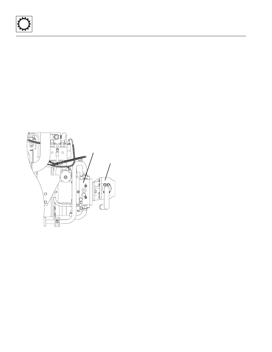
13. Loosen and remove both bolts holding the
implement pump (1) to the drive pump (2).
14. Pull the implement pump away from the drive pump.
15. Connect a lifting strap or chain to the top of the drive
pump, and to a suitable hoist or overhead crane.
Operate the hoist or crane to remove slack from the
chain, but DO NOT raise the drive pump at this time.
16. Loosen and remove the two bolts holding the drive
pump to the engine bellhousing.
17. Carefully remove the drive pump from the machine.
Avoid causing damage to the drive pump or
surrounding parts.
18. Lift the drive pump clear of the machine and lower it
onto suitable supports or secure it to a stand built
especially for drive pump or engine service. Secure
the drive pump so that it will not move or fall.
6.5.2
Drive Pump Inspection and Internal
Repair
Note: Contact the JLG Service Department if internal
drive pump repair is required.
6.5.3
Drive Pump Installation
1. Use a hoist or overhead crane and sling attached to
the drive pump. Raise and position the drive pump
within the chassis.
2. Align the input shaft, align the drive pump bolt holes
with the two holes in the bell housing. Install the two
bolts and washers and torque to 240 lb-ft (240 Nm).
3. Remove the hoist or overhead crane and sling.
4. Align the input shaft, align the bolt holes of the
implement pump to the drive pump. Install the two
bolts and washers and torque to 160 lb-ft (217 Nm).
5. Connect the drive pump shift solenoid wiring
harness connectors.
6. Secure the wiring harness to the drive pump
housing.
7. Uncap and connect all the hydraulic hoses and
tubes.
8. Install the rear cover and belly pan.
9. Refill the hydraulic oil reservoir. Refer to Section 8.5,
10. Connect the (-) negative battery cable.
11. Start engine and check for any hydraulic leaks.
12. Close and secure the engine cover.
MX0870
1
2