6 auxiliary electric cable - three section, 1 electrical wire data, 2 electrical cable removal – JLG 534D-10 User Manual
Page 45: 3 electrical cable installation, Auxiliary electric cable - three section, Electrical wire data, Electrical cable removal, Electrical cable installation
3.17
534D-9, 534D-10 & 544D
Boom
3.6
AUXILIARY ELECTRIC CABLE -
THREE SECTION
The electric cable is fed through the right side of the boom
assembly in a fashion similar to the auxiliary hydraulic
hoses. The electric cable lies adjacent to the hydraulic
hoses and moves in unison with them, whenever the
boom sections are extended and retracted. The
receptacle and socket connector are equipped with a
strain relief fitting to prevent the wires from pulling loose.
This strain relief is tie-wrapped to the cable.
DO NOT install a cable without the strain relief
connected.
The socket end of the electric cable is fastened to the
front boom head of the third boom section. It is secured
with a bracket at this location. A strain relief fitting is
installed at the cable take-up weldment and support.
These assemblies are located at the area adjacent to the
hydraulic hose take-up weldment.
The receptacle and socket are equipped with six contact
points. One contact point is usually extra and is plugged
using JLG part number 83481301. Refer to the following
chart for identification in the socket (as viewed from the
wire insertion end).
3.6.1
Electrical Wire Data
3.6.2
Electrical Cable Removal
1. Remove any attachment from the quick switch
assembly. Refer to Section 3.16.1, “Disconnecting
from an Attachment.”
2. Park the machine on a hard, level surface, fully
retract the boom, level the boom assembly, place the
transmission control lever in (N) NEUTRAL, engage
the park brake and shut the engine OFF.
3. Place a Do Not Operate Tag on both the ignition key
switch and the steering wheel, stating that the
machine should not be operated.
4. Open the engine cover. Allow the system fluids to
cool.
5. Remove the battery negative (-) cable from the
battery negative (-) terminal.
6. Unfasten the electrical socket and clamps at the
front of the third boom section.
7. Remove the socket from the electrical cable.
8. Tie a rope to the cable end; this will aid in
reinstallation.
9. Remove the hose guard from the right side roller at
the rear of the boom.
10. Pull the electric cable to the rear, free of the boom.
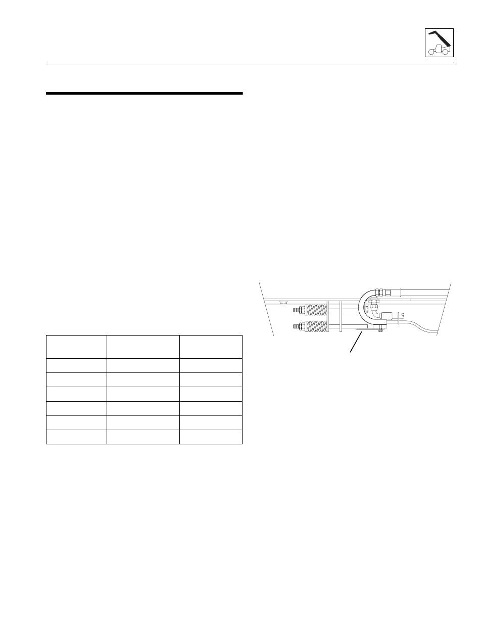
11. Remove the cable take-up weldment (4) and support
from the bottom front of the first boom section.
12. Pull the electric cable free of the boom through the
cable take-up weldment.
13. Remove the remaining cable clamps and unplug the
receptacle.
3.6.3
Electrical Cable Installation
It is assumed that the electric cable has been removed
and the relating parts left off the boom assembly. The
electric socket must not be installed at this time. The
cable must be well tensioned in the area between the
strain reliefs at the boom head on the third boom section
and the boom cable take-up brackets.
1. Tie the rope to the cable and feed it through the
strain relief fitting and cable take-up weldment tube,
then feed to the rear trough the cable take-up
weldment located at the bottom front of the first
boom section. The cable lies in the bottom plate area
between the first and second boom sections.
2. Feed the electric cable around the right side hose
roller, through the top protection channel, then to the
boom head at the front of the third boom section.
3. Install the hose guard at the right side hose roller
located at the rear of the second boom section.
4. Feed the cable through the tube weldment at the
boom head at the third boom section and install the
Socket Body
Letter
Wire Color
Wire Function
“TM”
Orange
Panel
“A”
Blue
Open/Extra
“S”
Black
Mast
“RT”
Green
Swing
“LT”
Red
Side Shift
“C”
Green/Yellow
Ground
MX0300
4