JLG 534D-10 User Manual
Page 68
Boom
3.40
534D-9, 534D-10 & 544D
3. Fully collapse the hose carriers and secure together
using plastic tie wraps or nylon straps to keep them
from separating.
4. Install a sling around the balance point of the sub-
assembly. With a suitable lifting device, slowly insert
the sub-assembly into the front of the fourth boom
section.
5. Remove the first plastic tie wrap or nylon strap as the
hydraulic sub-assembly is being inserted into the
front of the fourth boom section.
6. Continue inserting the hydraulic sub-assembly and
removing the plastic tie wraps or nylon straps until
the sub-assembly is fully inserted into the boom.
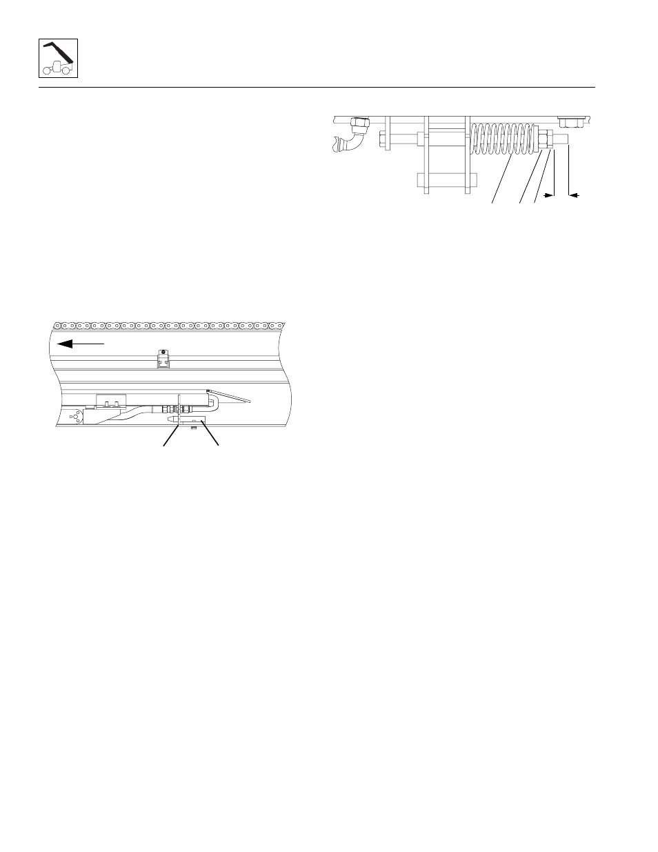
7. Verify that the bottom bracket (2) on the sub-
assembly is in place on the bottom plate (3) of the
fourth boom section.
8. Install the cap screws, washers and nuts to the sub-
assembly bracket at the rear of the third boom
section.
9. Install both cap screws and locknuts to the sub-
assembly bracket at the front of the fourth boom
section.
10. Uncap and reconnect the previously labeled tilt and
auxiliary hydraulic hoses to the proper fittings at the
rear of the hydraulic sub-assembly.
11. Uncap and reconnect the previously labeled tilt and
auxiliary hydraulic hoses to the proper fittings at the
front of the fourth boom section.
12. If equipped, reconnect any electrical connections at
the front and rear of the boom assembly.
13. Install the hose take-up compression springs (4) at
the bottom of the first boom section. Tighten the
adjusting nut (5) to measure 1 inch (25.0 mm)(6)
between the face of the jam nut (7) and the end of
the end of the threads on the hose take-up
weldment.
14. Torque the jam nut against the adjusting nut to
100 ft-lbs.
MY2700
3
FRONT
2
MY2690
4
6
5 7