Figure 115 – Brocade Communications Systems Brocade MLX Series and Brocade Netlron XMR 53-1002373-02 User Manual
Page 181
Brocade MLX Series and Brocade NetIron XMR Hardware Installation Guide
163
53-1002373-02
Installing a Brocade MLX-4 router
3
Follow these steps to connect a DC power source:
1. Use a #1 Phillips screwdriver to remove the two screws that hold the transparent cover over
the power supply lugs, as shown in
.
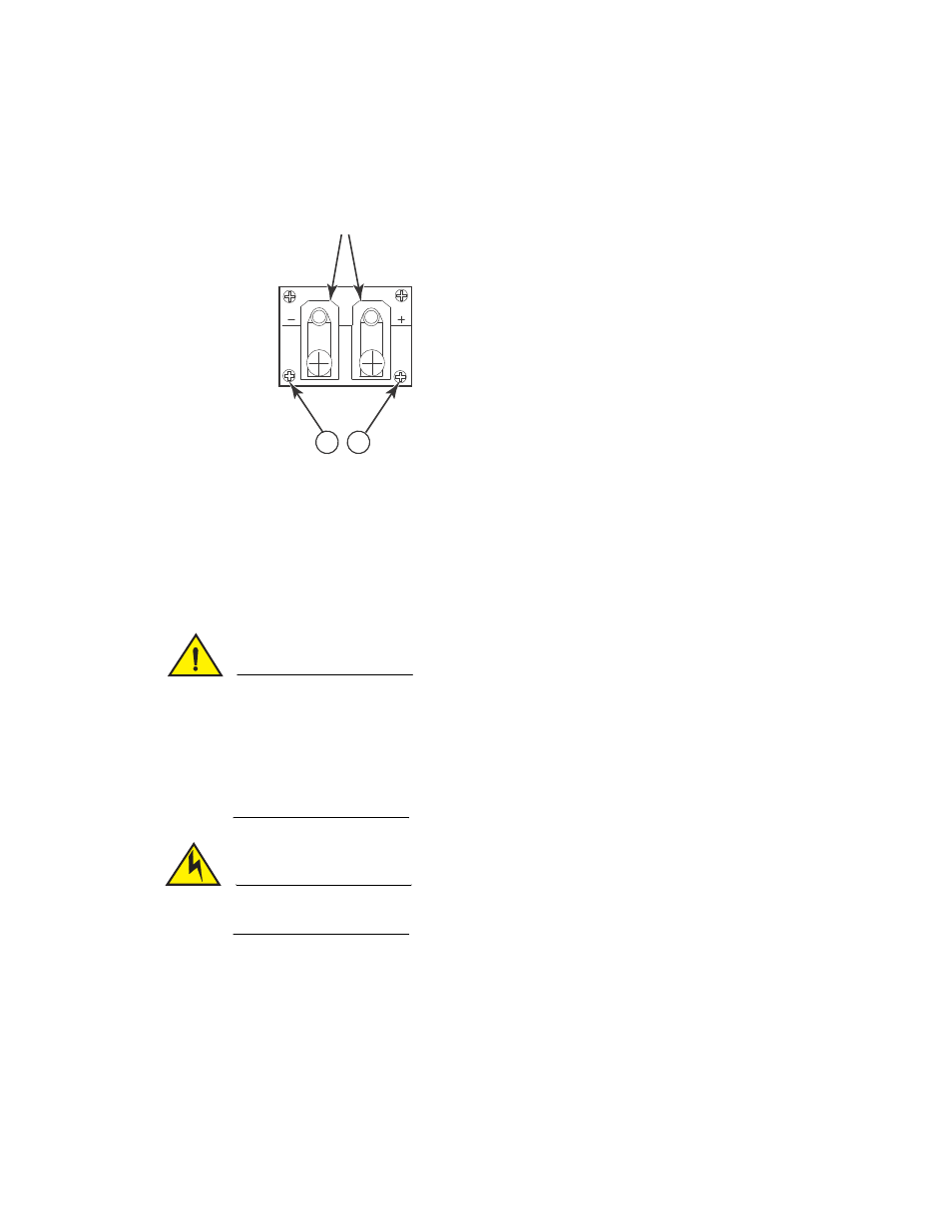
FIGURE 115
The Brocade MLX-4 DC power supply
2. Use a #2 Phillips screwdriver to remove the power lugs.
3. Crimp #8 AWG power supply wire into the power lugs and reconnect the lugs to the power
This equipment installation must meet NEC/CEC code requirements. Consult local authorities for
regulations.
CAUTION
For the NEBS-compliant installation of Brocade MLX 4-, 8-, and 16-slot routers with AC and DC
systems, use a ground wire of at least 6 American Wire Gauge (AWG). The ground wire should
have an agency-approved crimped connector (provided with the router) attached to one end, with
the other end attached to building ground. The connector must be crimped with the proper tool,
allowing it to be connected to both ground screws on the enclosure. Before crimping the ground
wire into the provided ground lug, ensure the bare copper wire has been cleaned and antioxidant
is applied to the bare wire.
CAUTION
To ensure adequate bonding when attaching the ground lug, a minimum of 20 PSI of torque is
required to be applied to the mounting hardware used to attach the ground lug.
1
Screws holding transparent cover
2 Power lug screws
1
1