Iii. semi-pak boiler assembly warning – Burnham Independence IN10 User Manual
Page 13
1
III. Semi-Pak Boiler Assembly
WARNING
Installation of this boiler should be undertaken
only by trained and skilled personnel from a
qualified service agency.
A.
Remove Crate
1. Remove all hold down screws and brackets.
2. Slide boiler to rear of skid and carefully remove
from crate skid onto 2 inch thick piece of wood and
then onto floor. Do not bump boiler jacket against
floor.
3. Do not drop boiler at any time.
B.
Move Boiler To Permanent Position. Refer to Section
I: Pre-Installation.
C.
Identify Trim and Controls
FIRST - Determine controls ordered with boiler and
refer to appropriate section(s) following:
There are two ordering methods for trim and controls:
1. EZ–Connect Carton (either steam or water) includes
trim, controls, wiring and wiring instructions for
installation.
2. Separate Trim Carton (steam or water) and Control
Carton (steam or water). Only wiring requiring
special connections is provided. For wiring
requirements, refer to Section VIII: Electrical and
appropriate wiring diagram.
D.
Install Trim and Controls
Refer to appropriate paragraphs (following) for trim
and controls to be installed.
1. Steam Boiler with Probe Low Water Cutoff
a. Install pressure limit control into Tapping "H"
with siphon, ¾" x ¼" hex bushing, ¾" elbow and
¾" x 3" nipple provided. See Figures 1 and 2.
DO NOT TWIST CONTROL. Use wrench on
hex fitting located at bottom of control. See
Figure 18.
b. The L404F pressure limit employs a snap action
switch and does not require leveling. See Figure
18.
c. Install pressure gauge into Tapping "B" (½ NPT
bushed to ¼ NPT). See Figures 1 and 2. Tighten
with wrench applied to square shank on back of
gauge. DO NOT APPLY PRESSURE ON
GAUGE CASE since this may destroy
calibration of gauge.
d. Install Low Water Cutoff Probe into Tapping "K"
(¾ NPT). HANDLE PROBE WITH CARE.
e. Attach Low Water cutoff Control to Probe by
following instructions packed with control.
f. Install gauge glass fittings into Tappings "C"
(½ NPT). See Figures 1 and 2. Lower fitting has
small drain valve.
g. Install gauge glass and protective rods in fittings.
h. Attach "Lowest Permissible Water Level" Plate
with sheet metal screws in location indicated in
Figure 9.
i. Attach "Frequent Water Addition" Label above
the "Lowest Permissible Water Level" Plate.
2. Steam Boiler with McDonnell & Miller 67 Float
Low Water Cutoff
a. Install Low Water Cutoff, see instructions packed
with control.
i. Screw brass nipples with union halves into
Tappings "C" (½ NPT). See Figure 1 and 2.
ii. Attach Gauge Glass/Low Water Cutoff
Assembly to union halves.
iii. Affix Blow-Down Card to Jacket Left Side
Panel adjacent to low water cutoff.
iv. Provide blow down discharge piping.
b. Attach street elbow siphon and pressure limit
control to low water cutoff. DO NOT TWIST
CONTROL. Use wrench on hex fitting located at
bottom of control.
c. The L404F pressure limit employs a snap action
switch and does not require leveling. See Figure
18.
d. Install pressure gauge into Tapping "H" (¾ NPT
bushed to ¼ NPT). See Figures 1 and 2. Tighten
with wrench applied to square shank on back of
gauge. DO NOT APPLY PRESSURE ON
GAUGE CASE since this may destroy
calibration of gauge.
e. Attach "Lowest Permissible Water Level" Plate
with sheet metal screws in location indicated in
Figure 9.
f. Attach "Frequent Water Addition" Label above
the "Lowest Permissible Water Level" Plate.
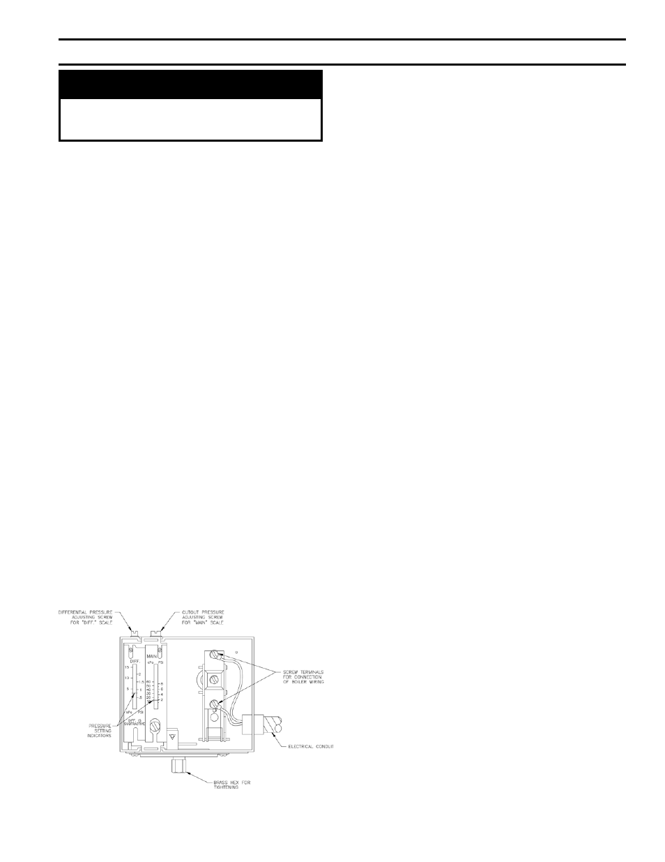
Figure 18: L404F Pressure Limit Control