Bryant 345MAV User Manual
Page 34
CAUTION:
These furnaces are equipped with a manual
reset limit switch in burner box. This switch will open
and shut off power to gas valve if an overheat condition
(flame rollout) occurs in burner enclosure. Correct inad-
equate combustion-air supply or improper venting condi-
tion and reset switch. DO NOT jumper this switch.
Failure to follow this caution will result in minor unit
operation or performance satisfaction.
Before operating furnace, check flame rollout manual reset switch
for continuity. If necessary, press button to reset switch.
II.
PRIME CONDENSATE TRAP WITH WATER
CAUTION:
Condensate trap must be PRIMED or
proper draining may not occur. The condensate trap has 2
internal chambers which can ONLY be primed by pour-
ing water into the inducer drain side of condensate trap.
Failure to follow this caution will result in minor unit
operation or performance satisfaction.
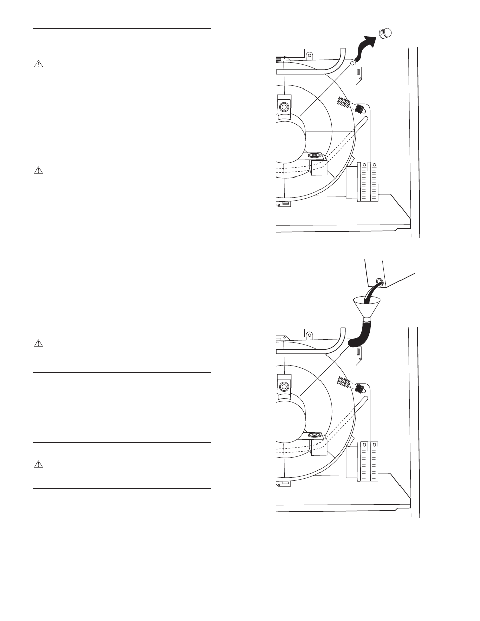
1. Remove upper inducer housing drain connection cap. (See
Fig. 44.)
2. Connect field-supplied 1/2-in. ID tube to upper inducer
housing drain connection.
3. Insert field-supplied funnel into tube.
4. Pour 1 quart of water into funnel/tube. Water should run
through inducer housing, overfill condensate trap, and flow
into open field drain. (See Fig. 45.)
5. Remove funnel and tube from inducer housing and replace
drain connection cap and clamp.
III.
PURGE GAS LINES
WARNING:
Never purge a gas line into a combustion
chamber. Never test for gas leaks with an open flame. Use
a commercially available soap solution made specifically
for the detection of leaks to check all connections. Failure
to follow this warning could result in fire, explosion,
personal injury, or death.
IV.
SEQUENCE OF OPERATION
If not previously done, purge lines after all connections have been
made and check for leaks.
Using the schematic diagram in Fig. 32, follow the sequence of
operation through the different modes. Read and follow the wiring
diagram very carefully.
CAUTION:
Furnace control must be grounded for
proper operation, or control will lock out. Control is
grounded throug green/yellow wire connected to gas
valve and burner box screw. Failure to follow this caution
will result in intermittent unit operation.
NOTE:
If a power interruption occurs during a call for heat (W),
the control will start a 90-second blower-only ON period two
seconds after power is restored, if the thermostat is still calling for
gas heating. The red LED light will flash code 12 during the
90-second period, after which the LED will be ON continuous, as
long as no faults are detected. After the 90-second period, the
furnace will respond to the thermostat normally.
The blower door must be installed for power to be conducted
through the blower door interlock switch ILK to the furnace
control CPU, transformer TRAN, inducer motor IDM, blower
motor BLWM, hot-surface igniter HSI, and gas valve GV.
1. Heating
(See Fig. 30 for thermostat connections.)
The wall thermostat
″
calls for heat
″
, closing the R to W
circuit. The furnace control performs a self-check, verifies
the pressure switch contacts PRS are open, and starts the
inducer motor IDM.
Fig. 45—Filling Condensate Trap
A99119
Fig. 44—Inducer Housing Drain Cap
A99118
—34—