Bryant 345MAV User Manual
Page 10
2. Inducer Housing Drain Tube
a. Remove and discard LOWER (molded) inducer housing
drain tube which was previously connected to conden-
sate trap.
b. Use inducer housing drain extension tube (violet label
and factory-supplied in loose parts bag) to connect
LOWER inducer housing drain connection to the con-
densate trap.
c. Determine appropriate length, cut, and connect tube.
d. Clamp tube to prevent any condensate leakage.
3. Relief Port Tube
a. Use smaller diameter tube (factory-supplied in loose
parts bag) to extend collector box tube (green label)
which was previously connected to the condensate trap.
b. Route extended collector box pressure tube to relief port
connection on the condensate trap.
c. Determine appropriate length, cut, and connect tube.
d. Clamp tube to prevent any condensate leakage.
C.
Condensate Trap Field Drain Attachment
Refer to Condensate Drain section for recommendations and
procedures.
D.
Pressure Switch Tubing
The LOWER collector box pressure tube (pink label) is factory
connected to the pressure switch for use when furnace is installed
in UPFLOW applications. This tube MUST be disconnected,
extended, rerouted, and then reconnected to the pressure switch in
HORIZONTAL LEFT applications.
NOTE:
See Fig. 10 or tube routing label on main furnace door to
check for proper connections.
Modify tube as described below.
1. Disconnect collector box pressure tube (pink label) attached
to pressure switch.
2. Use smaller diameter tube (factory-supplied in loose parts
bag) to extend tube disconnected in item 1.
3. Route extended tube:
a. Behind inducer housing.
b. Between blower shelf and inducer housing.
c. Behind inducer motor bracket.
d. Between inducer motor and pressure switch.
4. Determine appropriate length, cut, and reconnect tube to
pressure switch connection labeled COLLECTOR BOX.
E.
Condensate Trap Freeze Protection
Refer to Condensate Drain Protection section for recommenda-
tions and procedures.
F.
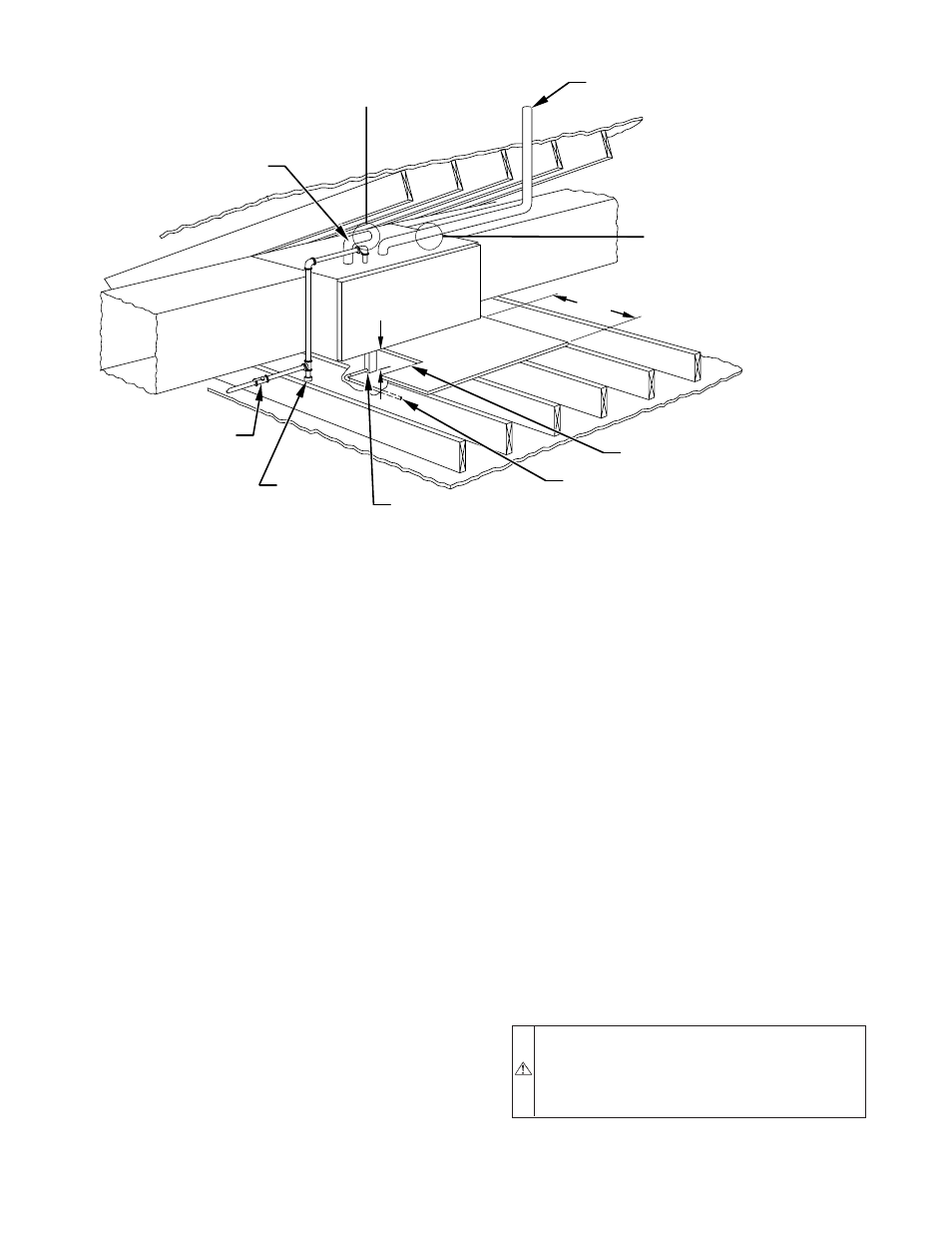
Construct a Working Platform
Construct working platform where all required furnace clearances
are met. (See Fig. 3 and 11.)
CAUTION:
The condensate trap MUST be installed
below furnace. See Fig. 5 for dimensions. The drain
connection to condensate trap must also be properly
sloped to an open drain. Failure to follow this caution will
result in intermittent unit operation.
NOTE:
Vent pipe length is restricted to a minimum of 5 ft. (See
Table 6.)
Fig. 11—Attic Location and Working Platform
A96184
VENT
MANUAL
SHUTOFF
GAS VALVE
SEDIMENT
TRAP
CONDENSATE
TRAP
DRAIN
ACCESS OPENING
FOR TRAP
30-IN. MIN
WORK AREA
A 12-IN. MIN HORIZONTAL PIPE
SECTION IS RECOMMENDED WITH
SHORT (5 TO 8 FT) VENT SYSTEMS
TO REDUCE EXCESSIVE
CONDENSATE DROPLETS FROM
EXITING THE VENT PIPE.
A 3-IN. MINIMUM CLEARANCE
TO COMBUSTION-AIR INTAKE
IS REQUIRED.
5
3
⁄
4
″
NOTE: LOCAL CODES MAY REQUIRE A DRAIN PAN UNDER THE
FURNACE AND CONDENSATE TRAP WHEN A CONDENSING
FURNACE IS INSTALLED ABOVE FINISHED CEILINGS.
COMBUSTION–AIR
INTAKE
—10—