Bryant 345MAV User Manual
Page 31
16. Use appropriate methods to seal openings where vent pipe
passes through roof or sidewall.
D.
Extended Exposed Sidewall Pipes
Sidewall vent pipe termination may be extended beyond area
shown in Fig. 40 and in outside ambient by insulating pipe as
indicated in Table 7.
1. Determine vent pipe diameter, as stated above, using total
pipe length and number of elbows.
2. Find appropriate temperature for your application and
furnace model using winter design temperature (used in
load calculations).
3. Determine required insulation thickness for exposed pipe
lengths.
NOTE:
Pipe length (ft) specified for maximum pipe lengths
located in unconditioned spaces cannot exceed total allowable pipe
length as specified in Table 6.
E.
Vent Termination
Vent pipe must terminate either through roof or sidewall. See
Table 8 for required clearances. See Fig. 39, 40, and 41 for exterior
piping arrangements.
F.
Multiventing
When 2 or more 345MAV Furnaces are vented near each other,
each furnace must be individually vented. NEVER common vent
or breach vent 345MAV furnaces.
VII.
CONDENSATE DRAIN
A.
General
Condensate trap is shipped installed in the blower shelf and factory
connected for UPFLOW applications. Condensate trap must be
RELOCATED for use in DOWNFLOW and HORIZONTAL
applications.
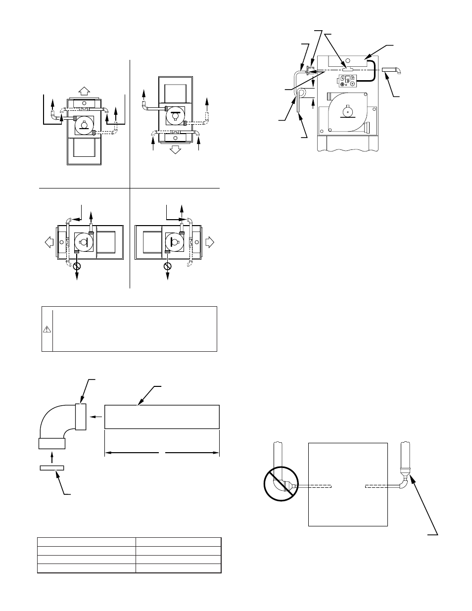
Fig. 34—Combustion-Air and Vent Pipe Connections
CAUTION:
Make sure there is adequate clearance (3-in.
minimum) to any fixed or loose objects in order to ensure
an adequate combustion-air supply. Failure to follow this
caution will result in intermittent unit operation or per-
formance satisfaction.
A96188
COMBUSTION-
AIR
COMBUSTION-
AIR
AIR
FLOW
VENT
VENT
VENT
AIR
FLOW
AIR
FLOW
AIR
FLOW
UPFLOW
DOWNFLOW
HORIZONTAL-LEFT DISCHARGE
HORIZONTAL-RIGHT DISCHARGE
Select 1 vent pipe connection and
1 combustion-air pipe connection.
COMBUSTION-
AIR
COMBUSTION-
AIR
COMBUSTION-
AIR
COMBUSTION-
AIR
NOTE:
Select 1 vent pipe connection and
1 combustion-air pipe connection.
NOTE:
VENT
VENT
VENT
Fig. 35—Combustion-Air Inlet Pipe Assembly
LENGTH OF STRAIGHT PIPE PORTION OF
COMBUSTION-AIR INLET PIPE ASSEMBLY (IN.)
CASING WIDTH
A
17-1/2
8-1/2
±
1/2
21
10-1/2
±
1/2
24-1/2
12
±
1/2
A96211
FIELD-SUPPLIED
2-IN. DIAMETER
PVC PIPE
FIELD-SUPPLIED
2-IN. DIAMETER
PVC 90
°
ELBOW
COMBUSTION-AIR DISC
(FACTORY-SUPPLIED IN
LOOSE PARTS BAG)
A
Fig. 36—Air Intake Housing Plug Fitting Drain
A96190
COMBUSTION–
AIR PIPE
BURNER
BOX
COMBUSTION–AIR
INTAKE HOUSING
3/8
″
ID TUBE
TRAP
TO OPEN
DRAIN
3/16
″
DRILL
HOUSING
PLUG
4
″
MIN
Fig. 37—Vent Pipe Diameter Transition Location and
Elbow Configuration
A93034
FURNACE
PIPE DIAMETER
TRANSITION IN
VERTICAL SECTION
NOT IN
HORIZONTAL
SECTION
—31—