Bryant 345MAV User Manual
Page 25
COMBUSTION AIR PIPE
CAUTION:
Combustion air must not be taken from
inside a structure that is frequently contaminated by
halogens, which include fluorides, chlorides, bromides,
and iodides. These elements are found in aerosols,
detergents, bleaches, cleaning solvents, salts, air freshen-
ers, adhesives, paint, and other household products.
Locate combustion-air inlet as far as possible from
swimming pool and swimming pool pump house.
Excessive exposure to contaminated combustion air will
result in safety and performance related problems.
NOTE:
Furnace combustion-air connections are sized for 2-in.
pipe. The combustion-air pipe will be 2-in. diameter in all
installations.
See Table 8 for required clearances.
Furnace combustion-air connection must be attached as shown in
Fig. 34. Combustion-air intake housing plug may need to be
relocated in some applications.
Combustion-air pipe must terminate outside of furnace casing with
1 elbow. Orient elbow so that opening faces down for upflow or
downflow applications. Orient elbow so that it faces sideways (left
or right) for horizontal left or horizontal right applications. (See
Fig. 34.) Maintain a 3-in. minimum clearance between the opening
of the combustion-air inlet pipe and any object.
NOTE:
All pipe joints must be cemented except attachment of
combustion-air inlet pipe to inlet housing connection, since it may
be necessary to remove pipe for servicing.
Install combustion air inlet pipe as follows:
1. Assemble combustion-air inlet pipe.
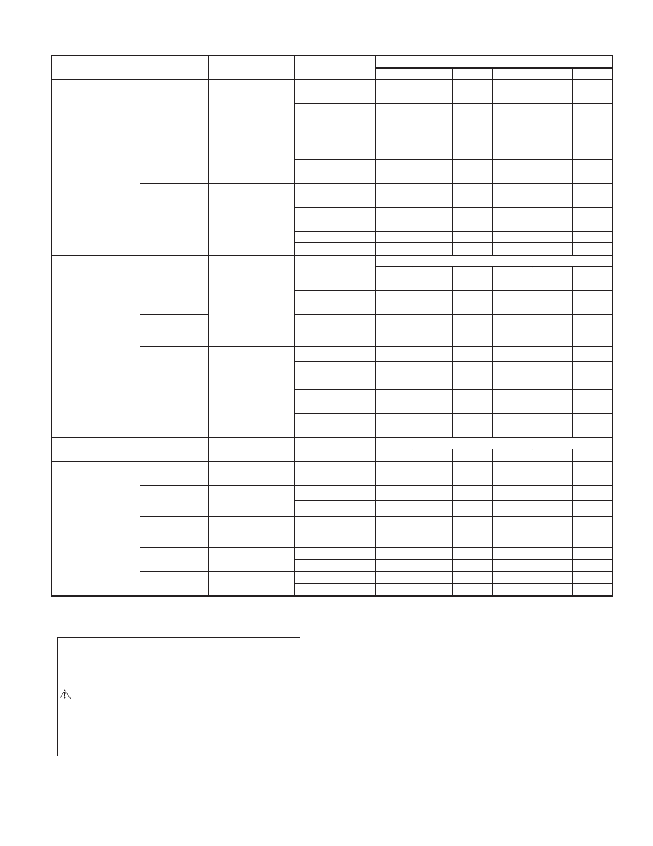
TABLE 6—MAXIMUM ALLOWABLE PIPE LENGTH (FT)
ALTITUDE (FT)
UNIT SIZE
TERMINATION
TYPE
PIPE DIA
(IN.)*
NUMBER OF 90° ELBOWS
1
2
3
4
5
6
0 to 2000
024040
036040
2 Pipe or 2-in
Concentric
1
5
NA
NA
NA
NA
NA
1-1/2
70
70
65
60
60
55
2
70
70
70
70
70
70
024060
036060
048060
2 Pipe or 2-in
Concentric
1-1/2
20
15
10
5
NA
NA
2
70
70
70
70
70
70
036080
048080
060080
2 Pipe or 2-in
Concentric
1-1/2
10
NA
NA
NA
NA
NA
2
55
50
35
30
30
20
2-1/2
70
70
70
70
70
70
048100
060100
2 Pipe or 3-in
Concentric
2
5
NA
NA
NA
NA
NA
2-1/2
40
30
20
20
10
NA
3
70
70
70
70
70
70
060120
2 Pipe or 3-in.
Concentric
2-1/2 one disk
10
NA
NA
NA
NA
NA
3†
45
40
35
30
25
20
3† no disk
70
70
70
70
70
70
ALTITUDE (FT)
UNIT SIZE
TERMINATION
TYPE
PIPE DIA
(IN.)*
NUMBER OF 90° ELBOWS
1
2
3
4
5
6
2001 to 3000
024040
036040
2 Pipe or 2-in
Concentric
1-1/2
67
62
57
52
52
47
2
70
70
70
70
70
70
2 Pipe or 2-in
Concentric
1–1/2
17
12
7
NA
NA
NA
024060
036060
048060
2
70
67
66
61
61
61
036080
048080
060080
2 Pipe or 2-in
Concentric
2
49
44
30
25
25
15
2-1/2
70
70
70
70
70
70
048100
060100
2 Pipe or 3-in
Concentric
2–1/2
35
26
16
16
6
NA
3
70
70
70
70
66
61
060120
2 Pipe or 3-in.
Concentric
3
14
9
NA
NA
NA
NA
3† no disk
70
70
63
56
50
43
4† no disk
70
70
70
70
70
70
ALTITUDE (FT)
UNIT SIZE
TERMINATION
TYPE
PIPE DIA
(IN.)*
NUMBER OF 90° ELBOWS
1
2
3
4
5
6
3001 to 4000
024040
036040
2 Pipe or 2-in
Concentric
1-1/2
64
59
54
49
48
43
2
70
70
70
70
70
70
024060
036060
048060
2 Pipe or 2-in
Concentric
1–1/2
16
11
6
NA
NA
NA
2
68
63
62
57
57
56
036080
048080
060080
2 Pipe or 2-in
Concentric
2
46
41
28
23
22
13
2-1/2
70
70
70
70
70
70
048100
060100
2 Pipe or 3-in
Concentric
2-1/2
33
24
15
14
5
NA
3
70
70
70
66
61
56
060120
2 Pipe or 3-in.
Concentric
3† no disk
65
58
51
44
38
31
4† no disk
70
70
70
70
70
70
See notes at end of table
—25—
→