Bryant 345MAV User Manual
Page 12
b. Remove and discard UPPER (molded) inducer housing
drain tube which was previously connected to conden-
sate trap.
c. Install cap and clamp on UPPER inducer housing drain
connection where molded drain tube was removed.
d. Use inducer housing drain extension tube (violet label
and factory-supplied in loose parts bag) to connect
LOWER inducer housing drain connection to conden-
sate trap.
e. Determine appropriate length, cut, and connect tube to
condensate trap.
f. Clamp tube to prevent any condensate leakage.
3. Relief Port Tube
Refer to Pressure Switch Tubing section for connection
procedure.
C.
Condensate Trap Field Drain Attachment
Refer to Condensate Drain section for recommendations and
procedures.
D.
Pressure Switch Tubing
One collector box pressure tube (pink label) is factory connected to
the pressure switch for use when furnace is installed in UPFLOW
applications. This tube MUST be disconnected and used for the
condensate trap relief port tube. The other collector box pressure
tube (green label) which was factory connected to the condensate
trap relief port connection MUST be connected to the pressure
switch in DOWNFLOW or HORIZONTAL RIGHT applications.
NOTE:
See Fig. 12 or tube routing label on main furnace door to
check for proper connections.
Relocate tubes as described below.
1. Disconnect collector box pressure tube (pink label) attached
to pressure switch.
2. Use smaller diameter tube (factory-supplied in loose parts
bag) to extend collector box pressure tube (green label)
which was previously connected to condensate trap relief
port connection.
3. Route extended collector box pressure tube behind inducer
motor bracket then between inducer motor and pressure
switch.
4. Connect collector box pressure tube (green label) to pres-
sure switch connection labeled COLLECTOR BOX.
5. Use remaining smaller diameter tube (factory-supplied in
loose parts bag) to extend collector box pressure tube (pink
label) which was previously connected to pressure switch.
6. Route this extended tube (pink label) to condensate trap
relief port connection.
7. Determine appropriate length, cut, and connect tube.
8. Clamp tube to relief port connection.
E.
Condensate Trap Freeze Protection
Refer to Condensate Drain Protection section for recommenda-
tions and procedures.
F.
Construct a Working Platform
Construct working platform where all required furnace clearances
are met. (See Fig. 3 and 11.)
CAUTION:
The condensate trap MUST be installed
below furnace. See Fig. 5 for dimensions. The drain
connection to condensate trap must also be properly
sloped to an open drain. Failure to follow this caution will
result in intermittent unit operation.
NOTE:
Vent pipe length is restricted to a minimum of 5 ft. (See
Table 6.)
NOTE:
A 12-in. minimum horizontal pipe section is recom-
mended with short (5 to 8 ft) vent systems. This recommendation
is to reduce excessive condensate droplets from exiting the vent
pipe. (See Fig. 11 or 38.)
LOCATION
I.
GENERAL
This furnace must:
•
be provided with air for combustion, ventilation, and dilution of
flue gases in accordance with the NFGC or NSCNGPIC. The
furnace MUST NOT be located in a confined space without
special provisions for dilution or ventilation air. See AIR FOR
COMBUSTION AND VENTILATION section.
•
be installed so the electrical components are protected from
water.
•
not be installed directly on any combustible material other than
wood flooring (refer to SAFETY CONSIDERATIONS).
•
be located so combustion-air and vent pipe maximum lengths
are not exceeded. Refer to Table 6.
•
be located where available electric power and gas supplies meet
specifications on the furnace rating plate.
•
be attached to an air distribution system and be located as close
to the center of the distribution system as possible. Refer to Air
Ducts section.
Fig. 13—Proper Condensate Drainage
A02146
UPFLOW OR DOWNFLOW
HORIZONTAL
FRONT
LEVEL (0
″
)
TO
1
⁄
2
″
MAX
MIN
1
⁄
4
″
TO
1
⁄
2
″
MAX
FRONT
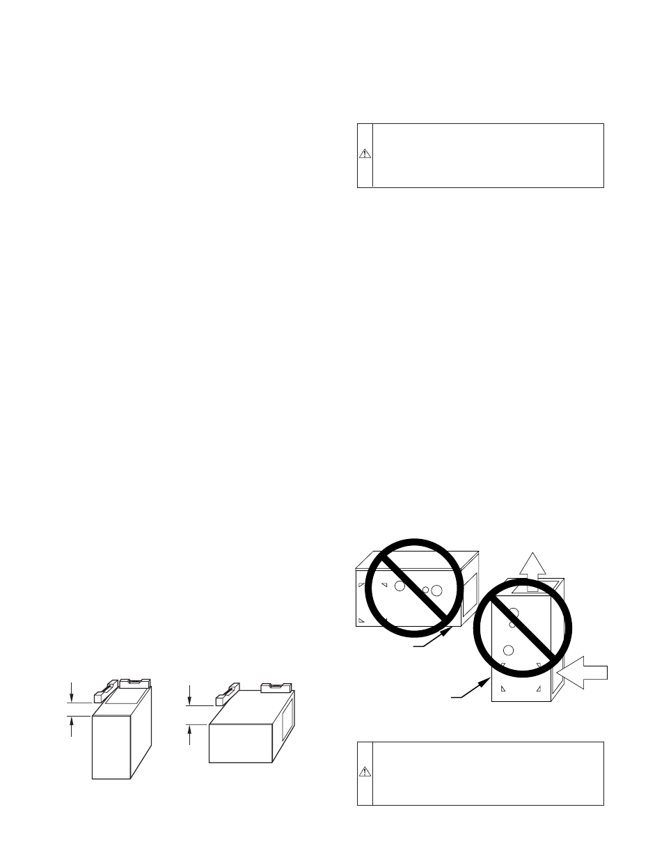
Fig. 14—Prohibit Installation on Back
WARNING:
Do not install furnace on its back. Safety
control operation will be adversely affected. Never con-
nect return-air ducts to back of furnace. Failure to follow
this warning could result in fire, personal injury, or death.
(See Fig. 14.)
A93043
FRONT
BACK
FRONT
B
A
C
K
—12—
→