Bryant 345MAV User Manual
Page 30
WARNING:
Vent pipe must be installed and fully
seated against inducer housing internal stop. Clamp must
be tightened to prevent any condensate leakage. Failure to
follow this warning could result in electrical shock, fire,
personal injury, or death.
NOTE:
A 2-in. diameter pipe must be used within the furnace
casing. Make all pipe diameter transitions outside furnace casing.
4. Be certain that mating surfaces of inducer housing connec-
tion, elastomeric coupling, and 2-in. diameter vent pipe are
clean and dry. Assemble the elastomeric (rubber) vent
coupling (with 2 loose clamps) onto inducer housing
connection. Insert the 2-in. diameter vent pipe through the
elastomeric (rubber) coupling and fully into inducer hous-
ing connection until it bottoms on the internal stop. Tighten
both clamps to secure the pipe to inducer housing. Tighten
the clamp screws to 15 in.-lb. of torque.
VENT EXTENSION PIPE
Some furnaces are supplied with a PVC vent extension pipe
(2-in. diameter by 12-in. long). This pipe has a built-in
channel to assist vent condensate disposal. When this vent
extension pipe is supplied, it must be used to connect the
field vent pipe to furnace inducer housing on ALL upflow
and downflow applications.
NOTE:
See label on vent extension pipe for proper installation.
This pipe may be shortened if an elbow is used to connect vent
extension tube to field-installed vent pipe.
5. Working from furnace to outside, cut pipe to required
length(s).
6. Deburr inside and outside of pipe.
7. Chamfer outside edge of pipe for better distribution of
primer and cement.
8. Clean and dry all surfaces to be joined.
9. Check dry fit of pipe and mark insertion depth on pipe.
NOTE:
It is recommended that all pipes be cut, prepared, and
preassembled before permanently cementing any joint.
10. After pipes have been cut and preassembled, apply gener-
ous layer of cement primer to pipe fitting socket and end of
pipe to insertion mark. Quickly apply approved cement to
end of pipe and fitting socket (over primer). Apply cement
in a light, uniform coat on inside of socket to prevent
buildup of excess cement. Apply second coat.
11. While cement is still wet, twist pipe into socket with 1/4
turn. Be sure pipe is fully inserted into fitting socket.
12. Wipe excess cement from joint. A continuous bead of
cement will be visible around perimeter of a properly made
joint.
13. Handle pipe joints carefully until cement sets.
14. Support vent piping a minimum of every 5 ft (3 ft for
SDR-21 or -26 PVC) using perforated metal hanging strap.
15. Slope vent pipe downward toward furnace a minimum of
1/4 in. per linear ft with no sags between hangers.
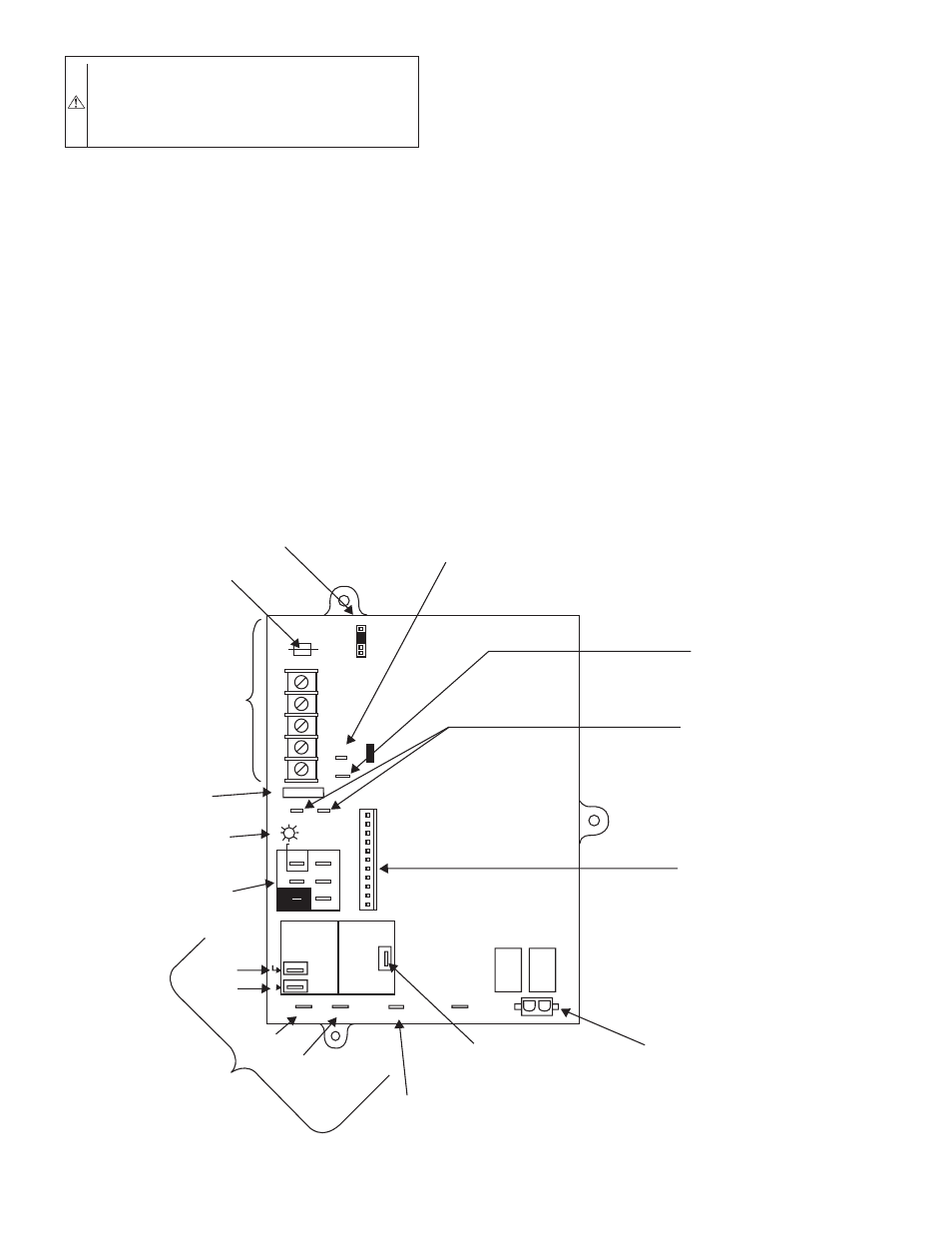
Fig. 33—Control Center
A02100
BL
W
NUETRAL
ST
A
TUS CODE LED
SEC-2 SEC-1
EAC-2 L2
FUSE 3-AMP
0.5 AMP@24VAC
HUM
TEST/TWIN
G Com
W
Y R
24V
120 180
90 150
BLOWER OFF-DELAY
PL
T 1
COOL HEA
T
SPARE-1 SPARE-2
EAC-1
1-AMP@
115VAC
PR-1
L1
PL2 1
24-V THERMOSTAT
TERMINALS
3-AMP FUSE
LED OPERATION &
DIAGNOSTIC LIGHT
115-VAC(L2)NEUTRAL
CONNECTIONS
COOL
HEAT
SPARE-1
SPARE-2
BLOWER SPEED
SELECTION TERMINALS
EAC-1 TERMINAL
(115-VAC 1.0 AMP MAX.)
115 VAC (L1) LINE
VOLTAGE CONNECTION
PL2-HOT SURFACE
IGNITER & INDUCER
MOTOR CONNECTOR
PL1-LOW VOLTAGE MAIN
HARNESS CONNECTOR
TRANSFORMER 24-VAC
CONNECTIONS
HUMIDIFIER TERMINAL
(24-VAC 0.5 AMP MAX.)
TWINNING AND/OR
COMPONENT TEST
TERMINAL
BLOWER OFF-DELAY
J2
J2 JUMPER
PL
T
—30—