Bryant 345MAV User Manual
Page 11
NOTE:
A 12-in. minimum horizontal pipe section is recom-
mended with short (5 to 8 ft) vent systems. This recommendation
is to reduce excessive condensate droplets from exiting the vent
pipe. (See Fig. 11 or 38.)
V.
HORIZONTAL RIGHT (SUPPLY-AIR DISCHARGE)
APPLICATIONS
A horizontal right furnace application is where furnace blower is
located to the left of combustion and controls section of furnace,
and conditioned air is discharged to the right.
CAUTION:
Local codes may require a drain pan under
entire furnace and condensate trap when a condensing
furnace is used in attic application or over a finished
ceiling. Failure to follow this caution will result in minor
property damage.
NOTE:
In Canada, installations shall be in accordance with
current NSCNGPIC Installation Codes and/or local codes.
A.
Condensate Trap Location
The condensate trap must be removed from the factory-installed
blower shelf location and relocated in selected application location
as shown in Fig. 2 or 12.
To relocate condensate trap from the blower shelf to desired
location, perform the following:
1. Remove 3 tubes connected to condensate trap.
2. Remove trap from blower shelf by gently pushing tabs
inward and rotating trap.
3. Install casing hole filler cap (factory-supplied in loose parts
bag) into blower shelf hole where trap was removed.
WARNING:
Casing hole filler cap must be installed in
blower shelf hole when condensate trap is relocated.
Failure to follow this warning could result in electrical
shock, fire, personal injury or death.
4. Install condensate trap into left-hand side casing hole by
inserting tube connection stubs through casing hole and
rotating until tabs snap into locking position.
5. Fill unused condensate trap casing holes with plastic filler
caps (factory-supplied in loose parts bag).
B.
Condensate Trap Tubing
NOTE:
See Fig. 12 or tube routing label on main furnace door to
check for proper connections.
1. Collector Box Drain Tube
a. Remove factory-installed plug from LOWER collector
box drain tube (blue and white striped label).
b. Install removed clamp and plug into UPPER collector
box drain tube (blue label) which was previously con-
nected to condensate trap.
c. Connect LOWER collector box drain tube (blue and
white striped label) to condensate trap. Tube does not
need to be cut.
d. Clamp tube to prevent any condensate leakage.
2. Inducer Housing Drain Tube
a. Remove factory-installed cap and clamp from LOWER
inducer housing drain connection.
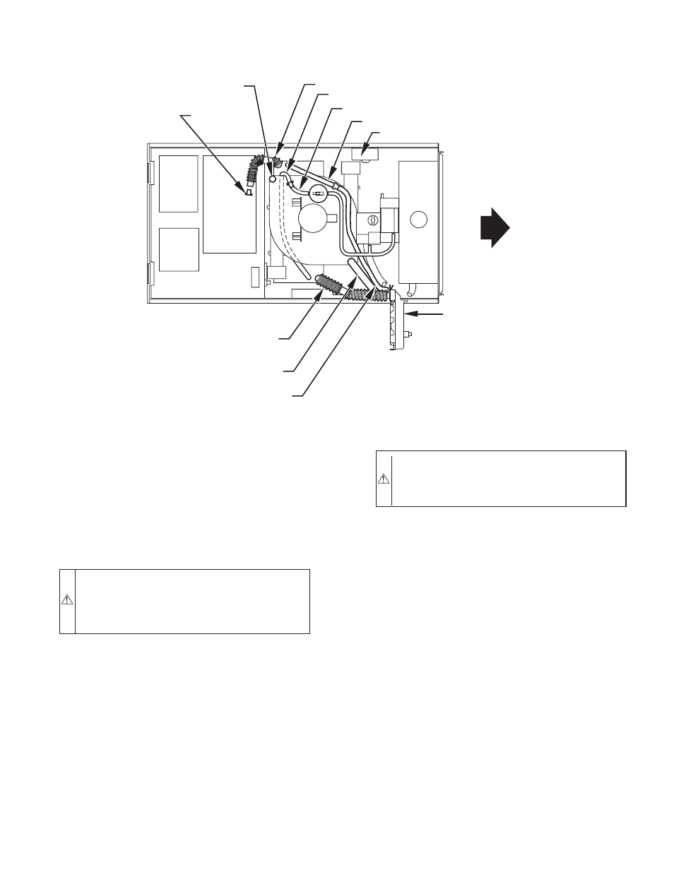
Fig. 12—Horizontal Right Tube Configuration
A00214
PLUG
COLLECTOR BOX DRAIN TUBE
(BLUE AND WHITE STRIPED)
INDUCER HOUSING
DRAIN TUBE (VIOLET)
COLLECTOR BOX
EXTENSION TUBE
COLLECTOR BOX TUBE (GREEN)
CAP
COLLECTOR BOX DRAIN TUBE (BLUE)
COLLECTOR BOX TUBE (PINK)
CONDENSATE
TRAP
COLLECTOR BOX EXTENSION TUBE
AUXILARY “J” BOX RELOCATED HERE
—11—