Installation – Bryant 345MAV User Manual
Page 2
Check Pressure Switch.................................................41
CHECKLIST......................................................................42
SAFETY CONSIDERATIONS
CAUTION:
Application of this furnace should be in-
doors with special attention given to vent sizing and
material, gas input rate, air temperature rise, unit leveling,
and unit sizing. Improper installation or misapplication of
furnace can require excessive servicing or cause prema-
ture component failure.
WARNING:
Improper installation, adjustment, alter-
ation, service, maintenance, or use can cause carbon
monoxide poisoning, explosion, fire, electrical shock, or
other conditions which may cause personal injury or
property damage. Consult a qualified installer, service
agency, local gas supplier, or your distributor or branch
for information or assistance. The qualified installer or
agency must use only factory-authorized and listed kits or
accessories when modifying this product. Failure to
follow this warning could result in electrical shock, fire,
personal injury, or death.
Installing and servicing heating equipment can be hazardous due to
gas and electrical components. Only trained and qualified
personnel should install, repair, or service heating equipment.
Untrained personnel can perform basic maintenance functions
such as cleaning and replacing air filters. All other operations must
be performed by trained service personnel. When working on
heating equipment, observe precautions in literature, on tags, and
on labels attached to or shipped with unit and other safety
precautions that may apply.
These instructions cover the minimum requirements and conform
to existing national standards and safety codes. In some instances,
these instructions exceed certain local codes and ordinances,
especially those that may not have kept up with changing residen-
tial construction practices. We require these instructions as a
minimum for a safe installation.
Wear safety glasses and work gloves. Have a fire extinguisher
available during start-up and adjustment procedures and service
calls.
CAUTION:
Sheet metal parts may have sharp edges or
burrs. Use care and wear appropriate protective clothing
and gloves when handling parts. Failure to follow this
caution could result in personal injury.
Recognize safety information. This is the safety-alert symbol
.
When you see this symbol on the unit and in instructions or
manuals, be alert to the potential for personal injury.
Understand these signal words DANGER, WARNING, CAU-
TION, and NOTE. These words are used with the safety-alert
symbol. DANGER identifies the most serious hazards which will
result in severe personal injury or death. WARNING signifies
hazards which could result in personal injury or death. CAUTION
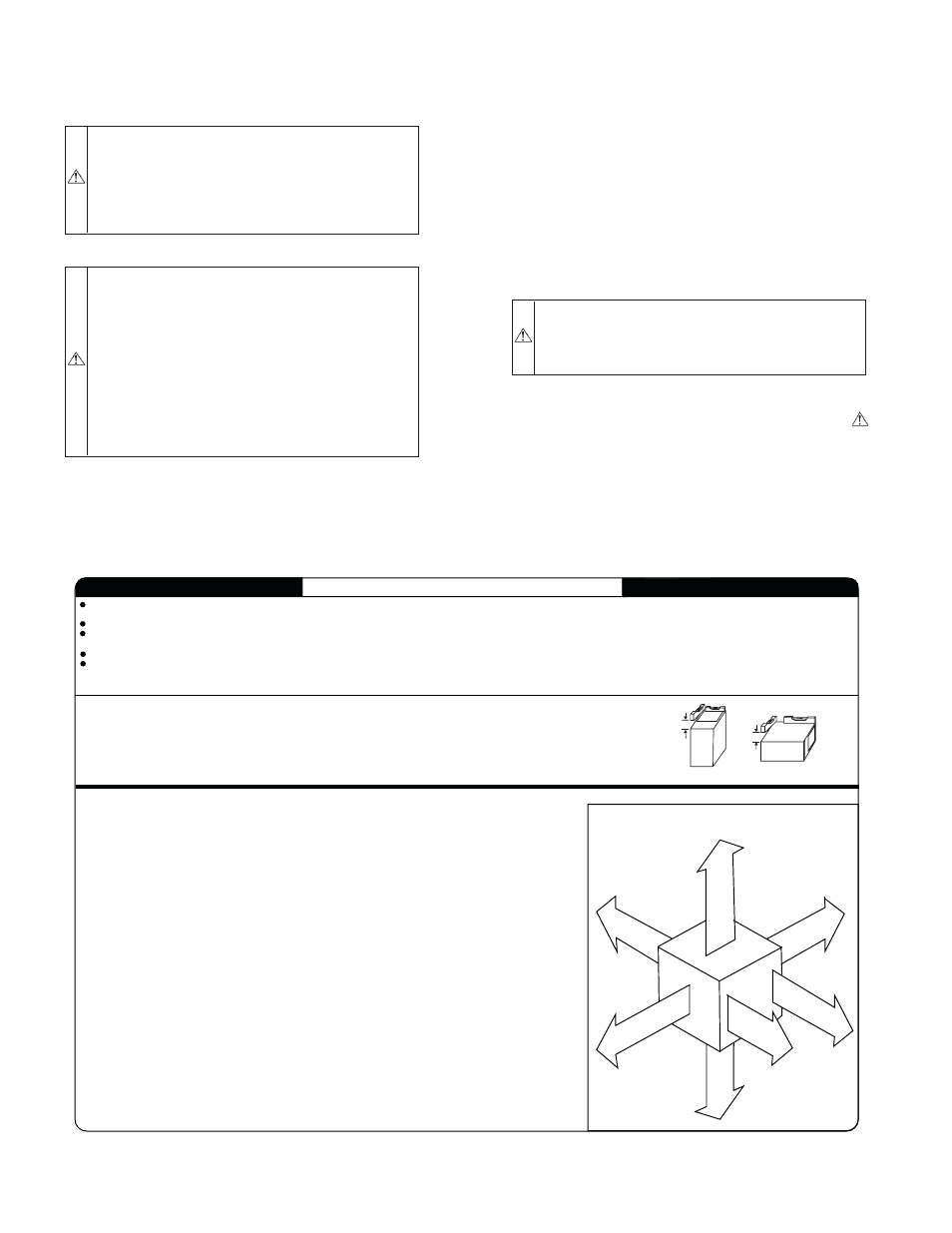
Fig. 3—Clearances to Combustibles
A02248
This forced air furnace is equipped for use with natural gas at altitudes 0 - 10,000 ft (0 - 3,050m), except 140 size furnaces are only approved for altitudes 0 - 7,000 ft.
(0 - 2,135m).
An accessory kit, supplied by the manufacturer, shall be used to convert to propane gas use or may be required for some natural gas applications.
This furnace is for indoor installation in a building constructed on site. This furnace may be installed in a manufactured (mobile) home when stated on rating plate and
using factory authorized kit.
This furnace may be installed on combustible flooring in alcove or closet at Minimum Inches Clearance To Combustible Construction as described below.
This furnace requires a special venting system. Refer to the installation instructions for parts list and method of installation. This furnace is for use with schedule-40 PVC,
PVC-DWV, CPVC, or ABS-DWV pipe, and must not be vented in common with other gas-fired appliances. Construction through which vent/air intake pipes may be
installed is maximum 24 inches (600 mm), minimum 3/4 inches (19 mm) thickness (including roofing materials).
MINIMUM INCHES CLEARANCE TO COMBUSTIBLE CONSTRUCTION
*
Minimum front clearance for service 30 inches (762mm).
140 size furnaces require 1 inch back clearance to combustible materials.
For installation on combustible floors only when installed on special base No. KGASB0201ALL,
Coil Assembly, Part No. CD5 or CK5, or Coil Casing, Part No. KCAKC.
Line contact is permissible only between lines formed by intersections of top and two sides of
furnace jacket, and building joists, studs, or framing.
Clearance shown is for air inlet and air outlet ends.
120 and 140 size furnaces require 1 inch bottom clearance to combustible materials.
Ø
Clearance in inches.
Vent clearance to
combustibles 0".
This furnace is approved for UPFLOW, DOWNFLOW and
HORIZONTAL installations.
*
BO
T
T
O
M
0"
Ø
3"
0"
§
0"
T
O
P/
PL
EN
U
M
1"
0"
§
30
MIN
ALL POSITIONS:
DOWNFLOW POSITIONS:
HORIZONTAL POSITIONS:
S I
D E
F
R
O
N
T
B
C
K
A
S
E
R V
I
E
C
F R
ON
T
S I
D E
U
F
R N
A C
E
Clearance arrows
do not change with
furnace orientation.
†
†
† †
UPFLOW OR
DOWNFLOW
1/2" MAX
LEVEL (0")TO
† †
328066-201 REV. A
LIT -TOP
INSTALLATION
§
For upflow and downflow applications, furnace must be installed level, or pitched within 1/2" of level. For a
horizontal application, the furnace must be pitched minimum 1/4" to maximum of 1/2" forward for proper
drainage. See Installation Manual for IMPORTANT unit support details on horizontal applications.
HORIZONTAL
FRONT
FRONT
MIN 1/4" TO 1/2" MAX
—2—