Bryant 345MAV User Manual
Page 27
2. Attach combustion-air inlet pipe.
a. Determine location of combustion-air intake pipe con-
nection to combustion-air intake housing as shown in
Fig. 34 for application.
b. Reposition combustion-air intake housing plug fitting in
appropriate unused intake housing connection.
c. Install pipe support (factory-supplied in loose parts bag)
into selected furnace casing combustion-air pipe hole.
Pipe support should be positioned at bottom of casing
hole.
d. Insert assembled combustion-air inlet pipe into intake
housing.
e. Make sure elbow is oriented in an acceptable direction
and that the minimum clearance of 3 in. is observed. (See
Fig. 34.)
f. Drill a 1/8-in. hole in 2-in. combustion-air inlet pipe
using hole in intake housing as a guide.
g. Install a field-supplied No. 6 or No. 8 sheet metal screw
into combustion-air pipe.
NOTE:
Do not attach combustion-air intake pipe permanently to
combustion-air intake housing since it may be necessary to remove
pipe for service of igniter or flame sensor.
COMBUSTION-AIR INTAKE HOUSING PLUG
FITTING
The combustion-air intake plug fitting must be installed in
unused combustion-air intake housing. This fitting must be
attached by using RTV sealant, or by drilling a 1/8-in. hole
in fitting, using hole in intake housing as a guide. Install a
field-supplied No. 6 or No. 8 sheet metal screw.
NOTE:
DO NOT OVERTIGHTEN SCREW. Breakage of intake
housing or fitting may cause air leakage to occur.
A plugged drain connection has been provided on this
fitting for use when moisture is found in combustion-air
intake pipe and combustion box. If use of this drain
connection is desired, drill out fitting’s tap plug with a
3/16-in. drill and connect a field-supplied 3/8-in. tube. This
tube should be routed to open condensate drain for furnace
and A/C (if used), and should be trapped. (See Fig. 36.)
VENT PIPE
NOTE:
Furnace vent pipe connections are sized for 2-in. pipe.
Any vent pipe size change should be made outside furnace casing
in vertical pipe. (See Fig. 37.) This allows proper drainage of vent
condensate.
Determine vent pipe diameter and maximum pipe lengths using
Table 6.
Furnace vent pipe connection must be attached as shown in Fig.
34. Inducer housing alternate vent cap may need to be relocated in
some applications.
NOTE:
Starting at furnace, slope vent pipe a minimum of 1/4 in.
per linear ft upward to termination(s) with no sags between
hangers.
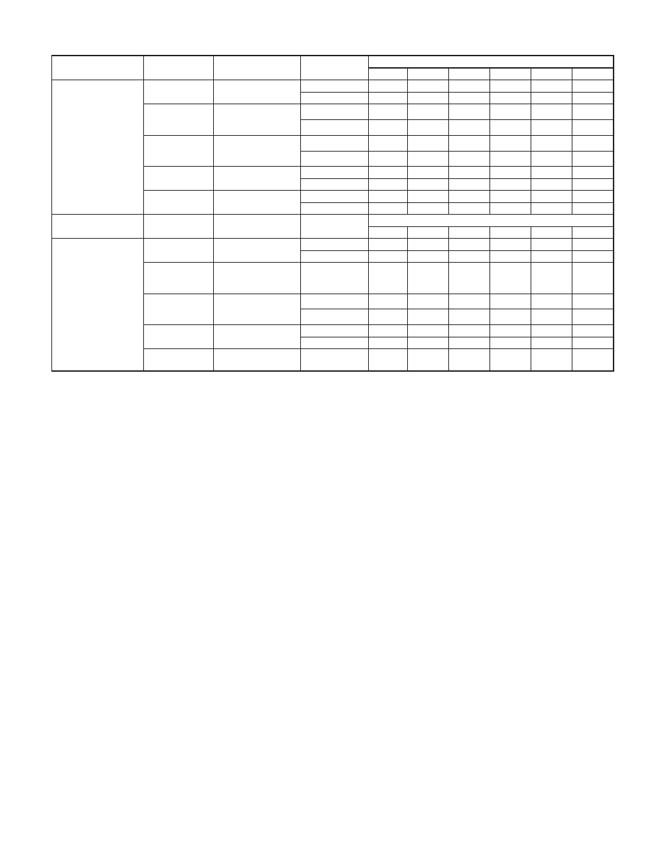
TABLE 6—MAXIMUM ALLOWABLE PIPE LENGTH (FT) (CONTINUED)
ALTITUDE (FT)
UNIT SIZE
TERMINATION
TYPE
PIPE DIA
(IN.)*
NUMBER OF 90° ELBOWS
1
2
3
4
5
6
8001 to 9000‡
024040
036040
2 Pipe or 2-in
Concentric
1-1/2
46
41
36
31
29
24
2
62
60
58
56
55
53
024060
036060
048060
2 Pipe or 2-in
Concentric
1-1/2
11
6
NA
NA
NA
NA
2
49
44
42
37
35
34
036080
048080
060080
2 Pipe or 2-in
Concentric
2
33
28
17
12
10
NA
2-1/2
62
60
58
56
55
53
048100
060100
2 Pipe or 3-in
Concentric
2-1/2
23
15
7
5
NA
NA
3
59
54
49
44
39
34
060120
2 Pipe or 3-in.
Concentric
3† no disk
10
NA
NA
NA
NA
NA
4† no disk
35
30
25
20
15
10
ALTITUDE (FT)
UNIT SIZE
TERMINATION
TYPE
PIPE DIA
(IN.)*
NUMBER OF 90° ELBOWS
1
2
3
4
5
6
9001 to 10,000‡
024040
036040
2 Pipe or 2-in
Concentric
1-1/2
42
37
32
27
25
20
2
57
55
53
51
49
47
024060
036060
048060
2 Pipe or 2-in
Concentric
2
45
40
38
33
31
29
036080
048080
060080
2 Pipe or 2-in
Concentric
2
30
25
14
9
7
NA
2-1/2
57
55
53
51
49
47
048100
060100
2 Pipe or 3-in
Concentric
2-1/2
21
13
5
NA
NA
NA
3
54
49
44
39
34
29
060120
2 Pipe or 3-in.
Concentric
4† no disk
10
5
NA
NA
NA
NA
Disk usage-Unless otherwise specified, use perforated disk assembly (factory-supplied in loose parts bag). If one disk is stated, separate 2 halves of perforated disk
assembly and use shouldered disk half. When using shouldered disk half, install screen side toward inlet box.
†Wide radius elbow.
‡Vent sizing for Canadian installations over 4500 ft (1370 m) above sea level are subject to acceptance by the local authorities having jurisdiction.
NA-Not Allowed; pressure switch will not make.
NOTES:
1. Do not use pipe size greater than those specified in table or incomplete combustion, flame disturbance, or flame sense lockout may occur.
2. Size both the combustion-air and vent pipe independently, then use the larger diameter for both pipes.
3. Assume two 45° elbows equal one 90° elbow. Long radius elbows are desirable and may be required in some cases.
4. Elbows and pipe sections within the furnace casing and at the vent termination should not be included in vent length or elbow count.
5. The minimum pipe length is 5 ft for all applications.
6. Use 3-in. diameter vent termination kit for installations requiring 4-in diameter pipe.
—27—