Bryant 345MAV User Manual
Page 32
Condensate trap MUST be used for all applications.
An external trap is not required when connecting the field drain to
this condensate trap.
The field drain connection (condensate trap or drain tube coupling)
is sized for 1/2-in. CPVC, 1/2-in. PVC, or 5/8-in. ID tube
connection.
Drain pipe and fittings must conform to ANSI standards and
ASTM D1785, D2466 or D2846. CPVC or PVC cement must
conform to ASTM D2564 or F493. Primer must conform to ASTM
F656. In Canada, use CSA or ULC listed schedule 40 CPVC or
PVC drain pipe, fittings, and cement.
When a condensate pump is required, select a pump which is
approved for condensing furnace applications. To avoid conden-
sate spillage, select a pump with an overflow switch.
CAUTION:
Unit must not be installed, operated, and
then turned off and left in an unconditioned structure
during cold weather when temperature drops to 32
degrees F and below unless drain trap and drain line have
adequate freeze protection. See Service and Maintenance
Instructions for winterizing procedures. (See Fig. 15.)
Failure to follow this caution will result in intermittent
unit operation.
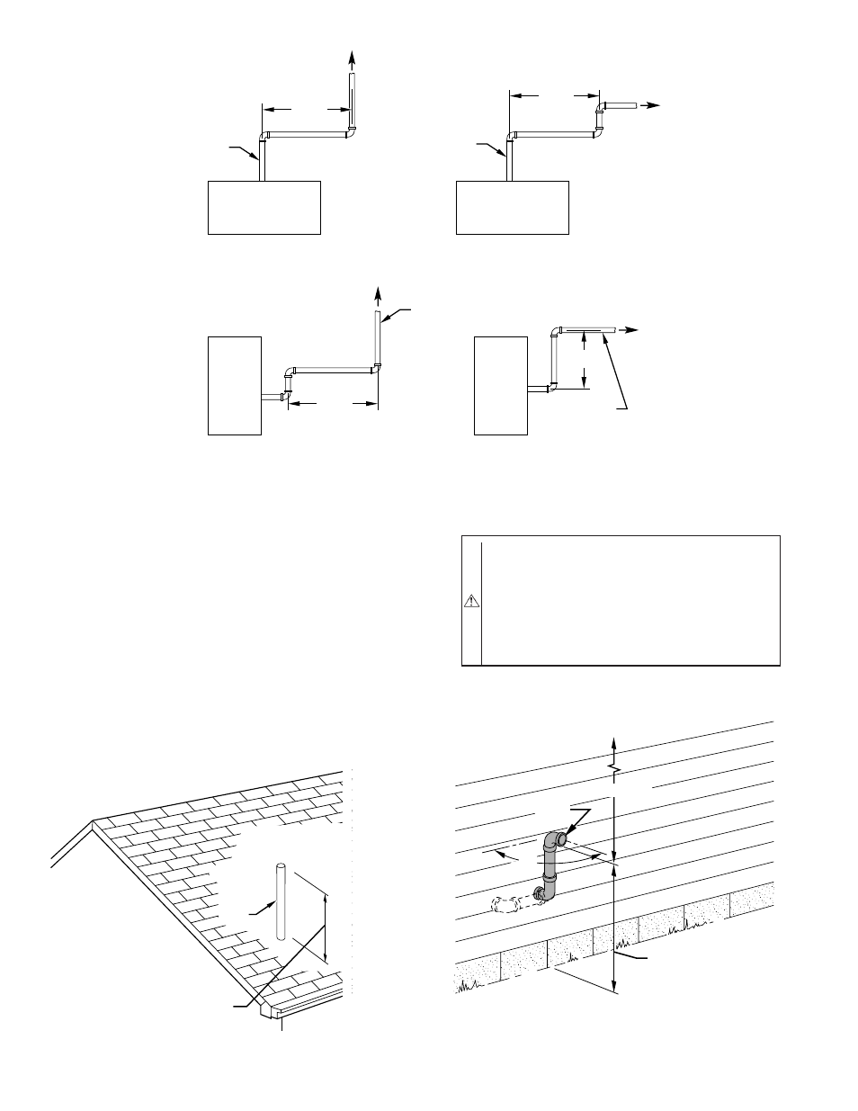
Fig. 38—Short Vent (5 to 8 Ft) System
A96189
HORIZONTAL TO ROOF
HORIZONTAL TO SIDEWALL
VERTICAL TO SIDEWALL
VERTICAL TO ROOF
VENT PIPE
VENT PIPE
VENT PIPE
VENT PIPE
12
″
MIN
12
″
MIN
12
″
MIN
12
″
MIN
NOTE: A 12-In. minimum offset pipe section is recommended with
short (5 to 8 ft) vent systems. This recommendation is to reduce
excessive condensate droplets from exiting the vent pipe.
ROOF
VENT
MAINTAIN 12-IN. MINIMUM
CLEARANCE ABOVE HIGHEST
ANTICIPATED SNOW LEVEL.
MAXIMUM OF 24 IN.
ABOVE ROOF.
A96191
Fig. 39—Roof Termination (Preferred)
MAINTAIN 12-IN.
CLEARANCE
ABOVE HIGHEST
ANTICIPATED SNOW
LEVEL OR GRADE,
WHICHEVER IS
GREATER.
90
°
VENT
12
″
MINIMUM
OVERHANG OR ROOF
A96192
Fig. 40—Sidewall Termination with 2 Elbows (Preferred)
—32—