Bryant 345MAV User Manual
Page 33
Furnace condensate is mildly acidic, typically in the pH range of
3.2 to 4.5. Due to corrosive nature of unneutralized condensate, a
condensate pH neutralizing filter may be desired. Check with local
authorities to determine if a pH neutralizer is required.
B.
Application
The furnace, A/C, and humidifier drains may be combined and
drained together. The A/C drain must have an external, field-
supplied trap prior to the furnace drain connection. All drain
connections (furnace, A/C, or humidifier) must be terminated into
an open or vented drain as close to the respective equipment as
possible to prevent siphoning of the equipment’s drain.
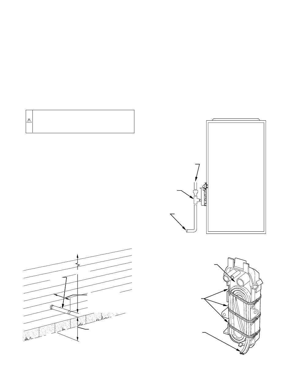
See Fig. 42 for example of possible field drain attachment using
1/2-in. CPVC or PVC tee for vent and A/C or humidifier drain
connection.
Outdoor draining of the furnace is permissible if allowed by local
codes. Caution should be taken when freezing ambient may freeze
drain pipe and prohibit draining.
WARNING:
Caution should be taken to prevent drain-
ing where slippery conditions may cause personal inju-
ries. Excessive condensate draining may cause saturated
soil conditions which may result in damage to plants.
C.
Condensate Drain Protection
Freezing condensate left in condensate trap and drain line may
cause cracks, and possible water damage may occur. If freeze
protection is required, use condensate freeze protection accessory
or equivalent 3 to 6 watt per ft at 120v and 40°F self-regulating,
shielded, and waterproof heat tape. See Installation Instructions
supplied with accessory or heat tape manufacturer’s recommenda-
tions.
1. Fold heat tape in half and wrap on itself 3 times.
2. Locate heat tape between sides of condensate trap back.
(See Fig. 43.)
3. Use wire ties to secure heat tape in place. Wire ties can be
positioned in notches of condensate trap sides. (See Fig.
43.)
4. Wrap field drain pipe with remaining heat tape, approxi-
mately 1 wrap per ft.
5. When using field-supplied heat tape, follow heat tape
manufacturer’s instructions for all other installation guide-
lines.
START-UP, ADJUSTMENTS AND SAFETY CHECK
I.
GENERAL
1. Furnace must have a 115-v power supply properly con-
nected and grounded. Proper polarity must be maintained
for correct operation.
NOTE:
Proper polarity must be maintained for 115-v wiring. If
polarity is incorrect, control center fault indicator light will flash
rapidly and furnace will not operate.
2. Thermostat wire connections at terminals R, W, G, and Y
must be made at 24-v terminal block on furnace control
center.
3. Natural gas service pressure must not exceed 0.5 psig
(14-in. wc), but must be no less than 0.16 psig (4.5-in. wc).
4. Blower access panel must be in place to complete 115-v
electrical circuit to furnace.
MAINTAIN 12-IN.
CLEARANCE
ABOVE HIGHEST
ANTICIPATED SNOW
LEVEL OR GRADE,
WHICHEVER IS
GREATER.
VENT
12
″
MINIMUM
OVERHANG OR ROOF
6-IN. MINIMUM
CLEARANCE BETWEEN
WALL AND END OF VENT
PIPE.
10-IN. MAXIMUM PIPE LENGTH
A96210
Fig. 41—Sidewall Termination with Straight Pipe
Fig. 42—Example of Field Drain Attachment
A94054
OPEN STAND
PIPE FOR
A/C OR
HUMIDIFIER
DRAIN
TEE
TO OPEN
DRAIN
Fig. 43—Condensate Trap Heat Tape
A93036
CONDENSATE TRAP
WIRE TIE(S)
HEAT TAPE
(3 WRAPS MINIMUM)
—33—