Bryant 345MAV User Manual
Page 22
C.
Accessories
1. Electronic Air Cleaner (EAC)
Two quick-connect terminals marked EAC-1 and EAC-2
are provided for EAC connection. (See Fig. 33.) These
terminals are energized with 115v (1.0-amp maximum)
during blower motor operation.
2. Humidifier (HUM)
A quick-connect terminal (HUM) and screw terminal (C
OM
24v) are provided for 24-v humidifier connection. (See Fig.
26.) HUM terminal is energized with 24v (0.5-amp maxi-
mum) After the inducer pre-purge period. (HK42FZoB
Control Board)
NOTE:
A field-supplied, 115-v controlled relay connected to
EAC terminals may be added if humidifier operation is desired
during blower operation.
VI.
VENTING
The 345MAV Furnaces require a dedicated, (one 345MAV fur-
nace only) sealed vent system. All air for combustion is taken from
the area adjacent to furnace, and all flue gases are discharged to
outdoor atmosphere.
A.
Removal of Existing Furnaces from
Common Venting Systems
When an existing Category I furnace is removed or replaced, the
original venting system may no longer be sized to properly vent
the remaining attached appliances. An improperly sized Category
I venting system could cause the formation of condensate in the
furnace and vent, leakage of condensate and combustion products,
spillage of combustion products into the living space, etc.
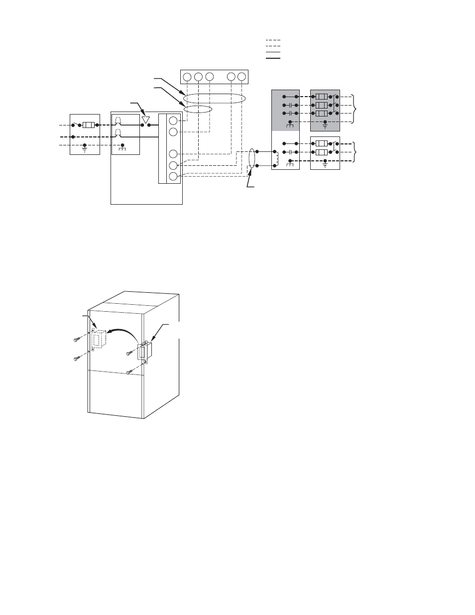
Fig. 30—Typical Heating and Cooling Application Wiring Diagram
A02174
115-V FIELD-
SUPPLIED
DISCONNECT
AUXILIARY
J-BOX
24-V
TERMINAL
BLOCK
THREE-WIRE
HEATING-ONLY
FIVE WIRE
NOTE 1
NOTE 2
FIELD-SUPPLIED
DISCONNECT
CONDENSING
UNIT
TWO
WIRE
FURNACE
C
O
N
T
R
O
L
R
G
COM
W
C
R
G
Y
GND
GND
FIELD 24-V WIRING
FIELD 115-, 208/230-, 460-V WIRING
FACTORY 24-V WIRING
FACTORY 115-V WIRING
208/230- OR
460-V
THREE
PHASE
208/230-V
SINGLE
PHASE
BLOWER DOOR SWITCH
WHT
BLK
WHT
BLK
NOTES:
Connect Y-terminal in furnace as shown for proper blower operation.
Some thermostats require a "C" terminal connection as shown.
If any of the original wire, as supplied, must be replaced, use
same type or equivalent wire.
W
Y
GND
THERMOSTAT
TERMINALS
1.
2.
3.
Fig. 31—Relocating J-Box
A00212
FACTORY
INSTALLED
LOCATION
ALTERNATE
FIELD
LOCATION
—22—