Bryant 345MAV User Manual
Page 28
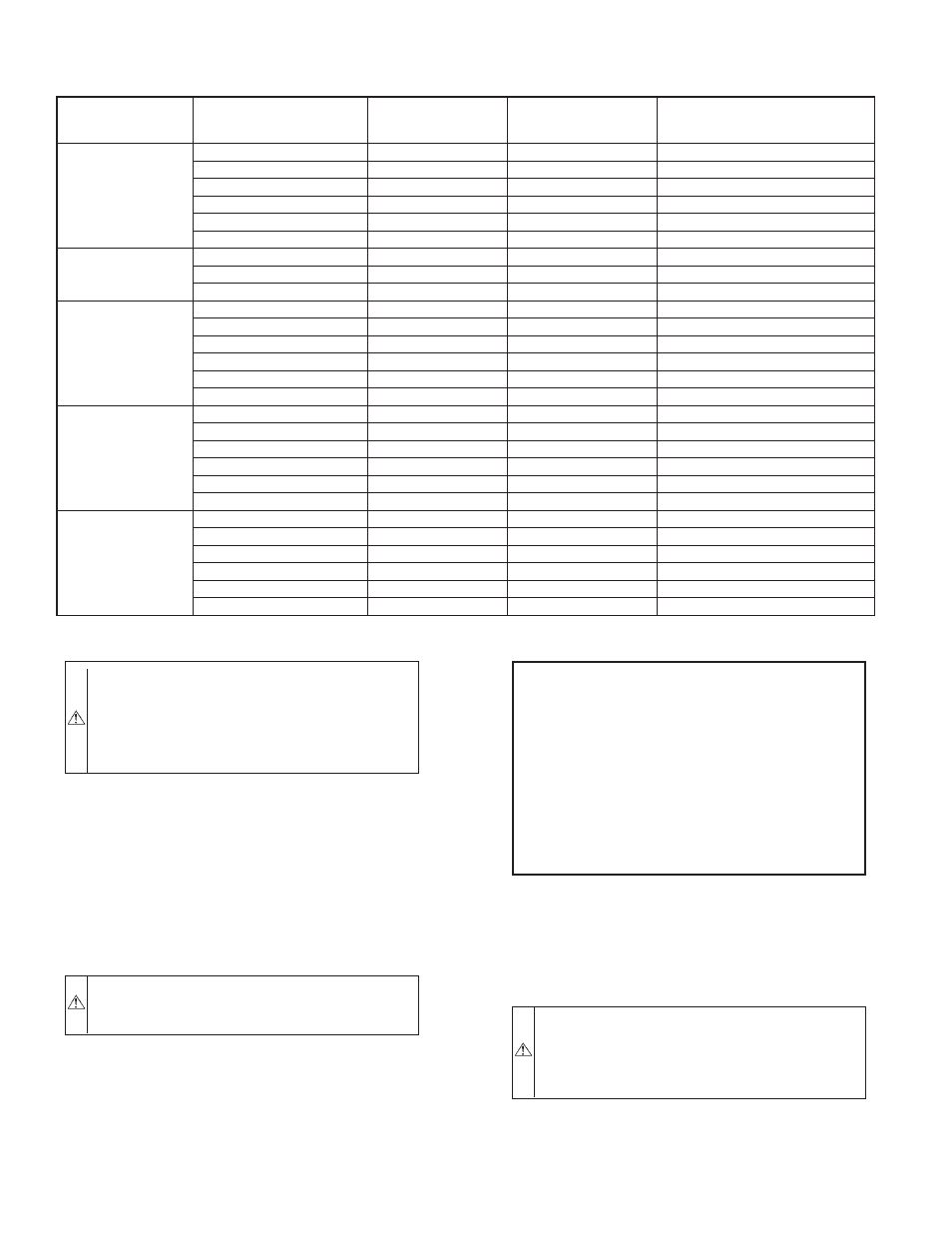
CAUTION:
When vent pipe is exposed to temperatures
below freezing, such as when it passes through an
unheated space or when a chimney is used as a raceway,
pipe must be insulated as described in Table 7 with
Armaflex-type insulation. Failure to follow this caution
will result in intermittent unit operation.
An abandoned masonry chimney may be used as a raceway for a
properly insulated and supported vent pipe. Each furnace must
have its own vent pipe and be terminated individually, as shown in
Fig. 41.
Other gas appliances with their own venting system may also use
the abandoned chimney as a raceway providing it is permitted by
local code, the current edition of the National Fuel Gas Code and
the vent or liner manufacturer’s installation instructions. Care must
be taken to prevent the exhaust gases from one appliance from
contaminating the combustion air of other gas appliances.
WARNING:
Vent pipes must be airtight and watertight.
Failure to follow this warning could result in property
damage, personal injury, or death.
NOTE:
The minimum vent pipe length for these furnaces is 5 ft.
Short pipe lengths (5-8 ft) may discharge water droplets. These
droplets may be undesirable, and a 12-in. minimum offset pipe
section is recommended to reduce excessive droplets from exiting
vent pipe outlet. (See Fig. 38.)
NOTE:
Do not count elbows or pipe sections in terminations or
within furnace. See shaded areas in Fig. 40.
EXAMPLE:
An 036080 size furnace located in Indianapolis, elevation
650 ft above sea level, could be installed in an application
requiring 3 elbows and 32 ft of vent pipe. Table 4 indicates
this application would allow a 2-in. diameter vent pipe. At
0-2000 ft elevation, 2-in. pipe is good for up to 35 ft with
3 elbows. If same installation were in Albuquerque, eleva-
tion 5250 ft above sea level, installation would require 2-1/2
in. vent pipe. At 5001- to 6000-ft elevation, 2-in. pipe is
allowed for up to 23 ft with 3 elbows, but 2-1/2 in. pipe can
be used for up to 70 ft with 3 elbows.
Install vent pipe as follows:
1. Determine location of vent pipe connection to inducer
housing as shown in Fig. 34 for application.
2. Reposition elastomeric (rubber) inducer housing outlet cap
and clamp to appropriate unused inducer housing connec-
tion. Tighten clamp.
WARNING:
Inducer housing outlet cap must be in-
stalled and fully seated against inducer housing. Clamp
must be tightened to prevent any condensate leakage.
Failure to follow this warning could result in electrical
shock, fire, personal injury, or death.
3. Install pipe support (factory-supplied in loose parts bag)
into selected furnace casing vent pipe hole. Pipe support
should be positioned at bottom of casing hole.
TABLE 7—MAXIMUM ALLOWABLE EXPOSED VENT PIPE LENGTH (FT) WITH AND WITHOUT INSULATION IN WINTER
DESIGN TEMPERATURE AMBIENT*
FURNACE
SIZE
WINTER DESIGN
TEMPERATURE
(°F)
MAX PIPE
DIAMETER
(IN.)
WITHOUT
INSULATION
WITH 3/8–IN. OR
THICKER INSULATION†
040
20
1.5
51
70
0
1.5
28
70
-20
1.5
16
70
20
2
45
70
0
2
22
70
-20
2
10
58
060
20
2
65
70
0
2
35
70
-20
2
20
70
080
20
2
55
55
0
2
48
55
-20
2
30
55
20
2.5
70
70
0
2.5
47
70
-20
2.5
28
70
100
20
2.5
40
40
0
2.5
40
40
-20
2.5
38
40
20
3
70
70
0
3
50
70
-20
3
28
70
120
20
3
70
70
0
3
61
70
-20
3
37
70
20
4
70
70
0
4
48
70
-20
4
23
70
* Pipe length (ft) specified for maximum pipe lengths located in unconditioned spaces. Pipes located in unconditioned space cannot exceed total allowable pipe length as
specified in Table 7.
† Insulation thickness based on R value of 3.5 per in.
—28—