Specification & design manual, Performance data – Sioux Chief 544 Series Deck Anchors User Manual
Page 6
05
1/4
(6.4)
3/8
(9.5)
1/2
(12.7)
5/8
(15.9)
3/4
(19.1)
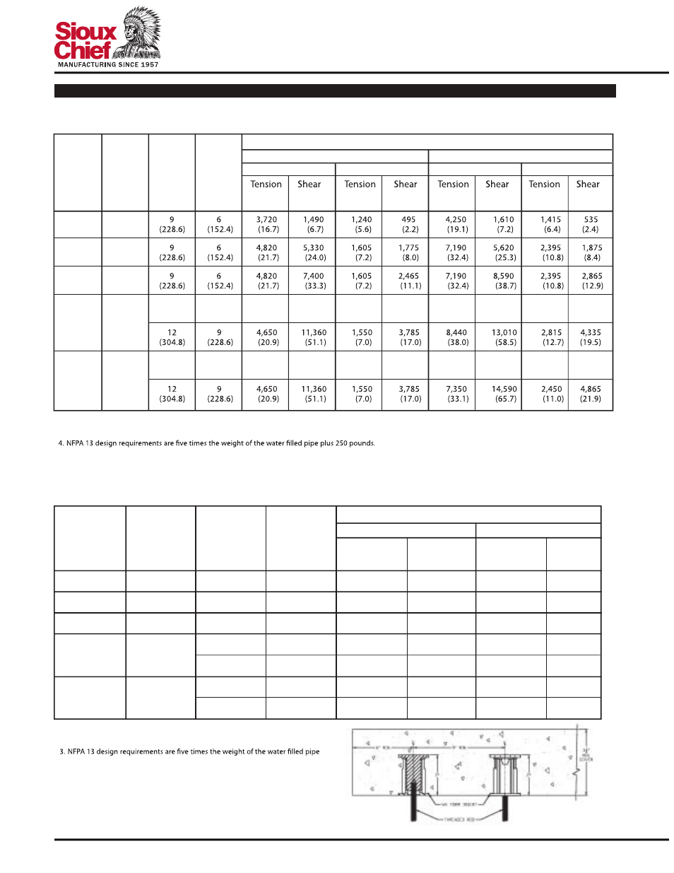
Ultimate and Allowable Load Capacities for Wood Deck Anchor Inserts Installed in Structural
Lightweight Concrete
1,2,3,4
2
(50.8)
2
(50.8)
2
(50.8)
2
(50.8)
2
(50.8)
9
6
4,650
–
1,550
–
8,440
–
2,815
–
(228.6)
(152.4)
(20.9)
(7.0)
(38.0)
(12.7)
9
6
4,650
–
1,550
–
7,350
–
2,450
–
(228.6)
(152.4)
(20.9)
(7.0)
(33.1)
(11.0)
Minimum Concrete Compressive Strength
(f´
c
)
Embed.
Depth
h
v
in.
(mm)
Minimum
Insert
Spacing
in.
(mm)
Minimum
End
Distance
in.
(mm)
Rod/
Insert
Diameter
d
in.
(mm)
lbs.
lbs.
lbs.
lbs.
lbs.
lbs.
lbs.
lbs.
(kN)
(kN)
(kN)
(kN)
(kN)
(kN)
(kN)
(kN)
3,000 psi (20.7 MPa)
4,500 psi (31.1 MPa)
Ultimate and Allowable Load Capacities for Wood Deck Anchor Inserts Installed
in Normal-Weight Concrete
1,2,3,4,5
1. Allowable load capacities listed are calculated using an applied safety factor of 3.0.
2. The allowable working load must be the lesser of the insert capacity or the steel strength of the threaded rod.
3. Linear interpolation may be used to determine ultimate loads for intermediate compressive strengths.
5. Allowable loads for anchors to resist short-term loads such as earthquake or wind may be increased by 33-1/3 percent for the duration of the load where permitted by code.
1/4
(
6.4
)
3/8
(
9.5
)
1/2
(
12.7
)
5/8
(
15.9
)
3/4
(
19.1
)
2
9
6
4,270
1,680
1,425
560
(
50.8
)
(228.6)
(152.4)
(19.2)
(7.6)
(6.4)
(2.5)
2
9
6
4,270
5,280
1,425
1,760
(
50.8
)
(228.6)
(152.4)
(19.2)
(23.8)
(6.4)
(7.9)
2
9
6
4,270
7,180
1,425
2,395
(
50.8
)
(228.6)
(152.4)
(19.2)
(32.3)
(6.4)
(10.8)
9
6
4,600
–
1,535
–
12
9
4,600
7,590
1,535
2,530
(304.8)
(228.6)
(20.7)
(34.2)
(6.9)
(11.4)
9
6
4,600
–
1,535
–
12
9
4,600
7,590
1,535
2,530
(304.8)
(228.6)
(20.7)
(34.2)
(6.9)
(11.4)
f´
c
≥
3,000 psi (20.7 MPa)
Embedment
Depth
h
v
in.
(mm)
Minimum
Insert
Spacing
in.
(mm)
Minimum
End
Distance
in.
(mm)
Rod/Insert
Diameter
d
in.
(mm)
Tension
Shear
Tension
Shear
lbs.
lbs.
lbs.
lbs.
(kN)
(kN)
(kN)
(kN)
Ultimate Load
Allowable Load
2
(
50.8
)
2
(
50.8
)
1. Allowable load capacities listed are calculated using an applied safety factor of 3.0.
2. The allowable working load must be the lesser of the insert capacity or the steel
strength of the threaded rod.
plus 250 pounds.
4. Allowable loads for anchors to resist short-term loads such as earthquake or wind
may be increased by 33-1/3 percent for the duration of the load where permitted
by code.
SPECIFICATION & DESIGN MANUAL
PERFORMANCE DATA
24110 South Peculiar Drive
PECULIAR, MO 64078
800.821.3944
FAX: 800.758.5950 WWW SIOUXCHIEF.COM
Ultimate Load
Allowable Load
Ultimate Load
Allowable Load
(228.6)
(228.6)
(152.4)
(152.4)
(20.7)
(20.7)
(6.9)
(6.9)