Nugget 200 spool valves – Norgren 200 Series Nugget Spool Valves User Manual
Page 34
Nugget 200 Spool Valves
VAL-10-34
Littleton, CO USA
Phone: 303-794-2611
www.norgren.com
Important:
1.Solenoid operated 2-position detent and
nondetent, and 3-position spring centered
valves can be combined in the same stack.
2.Plain stacking valves with common port 1
only and plain valves with common ports 1, 3
and 5 can be combined in one stack if
grouped together at opposite ends.
3.A stack or group of valves with common port
1 only must have isolating plugs installed in
the manifolding exhaust ports (3 and 5)
between each valve and each of the end
plates. Two exhaust port isolating plugs are
furnished with each valve. Installation need
not be specified on orders for factory
assembled stacks as this will be done
automatically.
4.Isolating plugs furnished in the end plate kit
at no extra cost can be placed between two
stacking valves to block the common ports
and separate a section of the valve stack to
accommodate two different input pressures.
One pressure is brought in from the front end
plate and the second pressure from the end
plate in the back. (Specify on order form
under “Special Instructions” where to install
isolating plugs.)
5.Ports 1, 3 and 5 in one end plate can be
plugged if so specified on order under
“Special Instructions”.
Special Instructions – Factory Assembled Stacking Valves
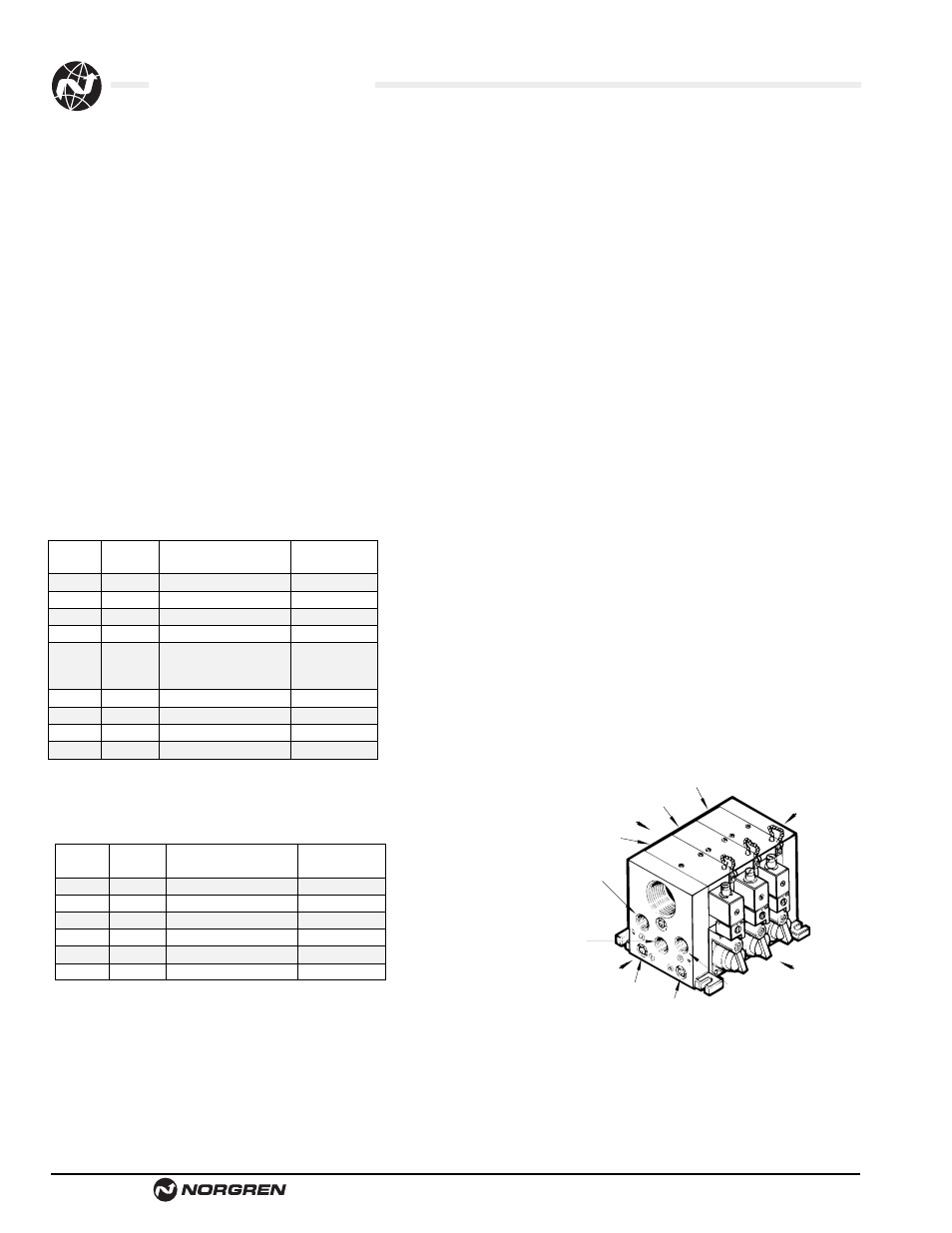
For Ordering purposes the valve stack is oriented as shown in
column two:
Unless otherwise noted:
1.Cylinder (outlet) ports are oriented toward the bottom
2.The 1 2 operator is on the left side, the
1 4 operator on the right side.
3.Valves are listed from the FRONT to
the BACK
Example 1: One stacking valve assembly with common inlet and
exhaust (ports 1, 3 and 5) and junction boxes with
solenoid operators with indicator lights. Isolating plugs
for two different working pressures installed between
valves 4 and 5.
Example 2: One Combination stacking valve assembly without
junction boxes. Valves on one end of stack with
common inlet and exhaust (ports 1, 3 and 5), and on
the opposite end with common inlet only (port 1).
Answer Example 1
Answer Example 2
Note:
Mufflers or filter nuts should be used in all valve body, end plate, or
solenoid operator exhaust ports to prevent entry of dirt and to
reduce the noise level of the exhausting air.
In wet locations, exhaust ports should not face upward to lessen
the possibility of liquids entering the unit.
Valve
Special
Pos. No. Quantity
Product Number
Instructions
1
1
K79DA50-KS6-KM1
2
1
K79DA50-KS6-KM1
3
1
K79DA50-KM6-KM6
4
1
K89EA50-KM8-KM8
Isolating Plugs
Common
Ports 1, 3 & 5
5
1
K79DA50-KM6-KM6
6
1
K79DA50-KM6-KM6
7
1
K79DA50-KM6-KM6
1
13295-50
End Plate Kit
Valve
Special
Pos. No. Quantity
Product Number
Instructions
1
1
K79DA00-KS6-KV2
2
1
K89EA00-KV0-KV0
3
1
K79EA00-KV2-KV2
4
1
K78DA00-KS6-KV2
5
1
K78EA00-KS6-KV2
1
13295-52
End Plate Kit
PORT 3
COMMON
EXHAUST
VALVE 1
VALVE 2
VALVE 3
FRONT
1 4 END
BACK
Common
Exhaust
1 2 END
PORT 1
COMMON
INLET
PORT 2
CYLINDER
PORT
PORT 4
CYLINDER
PORT
PORT 5
Factory Assembled Stacking Valve
Common Inlet & Exhaust