Pll filter, 1 general, Figure 23. pll block diagram – Cirrus Logic CS8416 User Manual
Page 53: 2 external filter components, 1 general 18.2 external filter components, Pll filter” on
DS578F3
53
CS8416
18.PLL FILTER
18.1 General
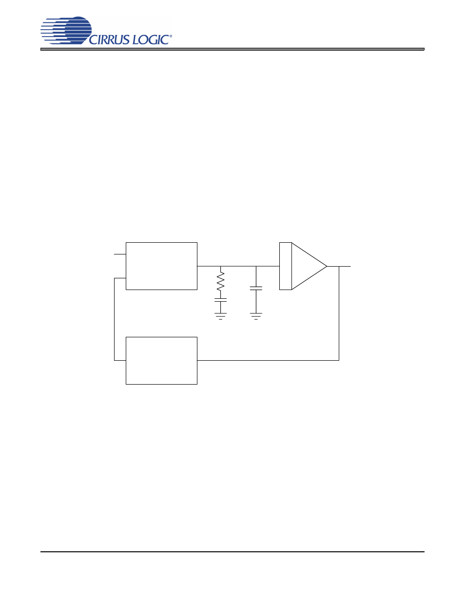
An on-chip Phase Locked Loop (PLL) is used to recover the clock from the incoming data stream.
is a simplified diagram of the PLL. When the PLL is locked to an bi-phase encoded input stream, it is updat-
ed at each preamble in the bi-phase encoded stream. This occurs at twice the sampling frequency, F
S
.
There are some applications where low jitter in the recovered clock, presented on the RMCK pin, is impor-
tant. For this reason, the PLL has been designed to have good jitter attenuation characteristics, as shown
in
. In addition, the PLL has been designed to only use the preambles (PDUR=0) of the bi-phase
encoded stream to provide lock update information to the PLL. This results in the PLL being immune to data
dependent jitter affects because the preambles do not vary with the data.
The PLL has the ability to lock onto a wide range of input sample rates with no external component changes.
If the sample rate of the input subsequently changes, for example in a varispeed application, the PLL will
only track up to ±12.5% from the nominal center sample rate. The nominal center sample rate is the sample
rate that the PLL first locks onto upon application of an bi-phase encoded data stream or after enabling the
CS8416 clocks by setting the RUN control bit. If the 12.5% sample rate limit is exceeded, the PLL will return
to its wide lock range mode and re-acquire a new nominal center sample rate.
18.2 External Filter Components
18.2.1 General
The PLL behavior is affected by the external filter component values.
and
shows the recom-
mended configuration of the two capacitors and one resistor that comprise the PLL filter. In
, the
component values shown have a high corner frequency jitter attenuation curve, take a short time to lock,
and offer good output jitter performance. Lock times are worst case for an Fsi transition of 192 kHz.
It is important to treat the PLL FLT pin as a low-level analog input. It is suggested that the ground end of
the PLL filter be returned directly to the AGND pin independently of the ground plane.
Phase
Comparator
and Charge Pump
÷N
VCO
RMCK
INPUT
C
RIP
C
FLT
R
FLT
Figure 23. PLL Block Diagram