Cs8416 – Cirrus Logic CS8416 User Manual
Page 19
DS578F3
19
CS8416
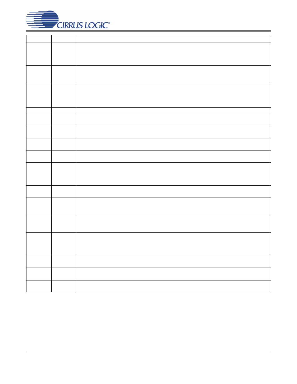
RXN
2
Negative AES3/SPDIF Input (Input) - Single-ended or differential receiver input carrying AES3 or
S/PDIF encoded digital data. Used along with RXP[3:0] to form an AES3 differential input. In single-
ended operation this should be AC coupled to ground through a capacitor. See
AES3/SPDIF/IEC60958 Receiver Components” on page 49
for recommended input circuits.
OMCK
22
System Clock (Input) - OMCK System Clock Mode is enabled by a transition (rising edge active) on
OMCK after reset. When enabled, the clock signal input on this pin is automatically output through
RMCK on PLL unlock. See
“OMCK System Clock Mode” on page 28
RMCK
21
Input Section Recovered Master Clock (Output) - Input section recovered master clock output
from the PLL. Frequency is 256x the sample rate (F
s
) when the U pin is pulled down by a 47 k
Ω
resistor to DGND. Frequency is 128x the sample rate (F
s
) when the U pin is pulled up by a 47 k
Ω
resistor to VL.
OSCLK
24
Serial Audio Output Bit Clock (Input/Output) - Serial bit clock for audio data on the SDOUT pin
OLRCK
25
Serial Audio Output Left/Right Clock (Input/Output) - Word rate clock for the audio data on the
SDOUT pin. Frequency will be the output sample rate (Fs)
SDOUT
23
Serial Audio Output Data (Output) - Audio data serial output pin. This pin must be pulled low to
DGND through a 47 k
Ω resistor to place the part in Hardware Mode.
RXSEL1
RXSEL0
7
8
Receiver MUX Selector (Input) - Used to select which pin, RXP[3:0], is used for the receiver input.
TXSEL1
TXSEL0
9
10
TX Pin MUX SELECTION (Input) - Used to select which pin, RXP[3:0], is passed to the TX pin out-
put. If TX passthrough is not used, the user should set it to output one of the unused receiver inputs.
TX
17
S/PDIF MUX Passthrough (Output) - Single-ended signal is resolved to full-rail, but is not de-jittered
before it is output. Output is set by TXSEL[1:0]. This pin is also used to select the type of phase
detector (PDUR) at reset. If TX passthrough is not used, the user should set it to output one of the
unused receiver inputs.
NV/RERR
11
Non-Validity Receiver Error/Receiver Error (Output) - Receiver error indicator. NVERR is selected
by a 47 k
Ω resistor to DGND. RERR is selected by a 47 kΩ resistor to VL.
AUDIO
12
Audio Channel Status Bit (Output) – When low, a valid linear PCM audio stream is indicated. See
“Non-Audio Detection” on page 31
. This pin is also used to select the serial port format (SFSEL1) at
reset.
96KHZ
13
96 kHz Sample Rate Detect (Output) - If the input sample rate is
≤ 48 kHz, outputs a “0”. Outputs a
“1” if the sample rate is
≥ 88.1 kHz. Otherwise the output is indeterminate. Also used to set the
Emphasis Audio Match feature at reset.
RCBL
14
Receiver Channel Status Block (Output) -Indicates the beginning of a received channel status block.
RCBL goes high two frames after the reception of a Z preamble, remains high for 16 frames and then
returns low for the remainder of the block. RCBL changes on rising edges of RMCK. Also used to set
the serial audio port to master or slave at reset.
C
16
Channel Status Data (Output) - Outputs channel status data from the AES3 receiver, clocked by the
rising and falling edges of OLRCK. Also used to select the serial port format (SFSEL0) at reset.
U
15
User Data (Output) - Outputs user data from the AES3 receiver, clocked by the rising and falling
edges of OLRCK. Also used to select the frequency of RMCK to either 256*F
s
or 128*F
s
at reset.
THERMAL
PAD
-
Thermal Pad - Thermal relief pad for optimized heat dissipation.
Pin Name
Pin #
Pin Description