3 temperature sensor calibration, 1 temperature offset and gain calibration, Figure 20. t register vs. force temp – Cirrus Logic CS5490 User Manual
Page 54: 3 tem, Perature sensor calibration, Cs5490
CS5490
54
DS982F3
6) If the phase offset is negative, then the delay should
be added only to the current channel. Otherwise, add
more delay to the voltage channel than to the current
channel to compensate for a positive phase offset.
Once the phase offset is known, the CPCC and FPCC
bits for that channel are calculated and programmed in
the PC register.
CPCC bits are used if either
• The phase offset is more than 1 output word rate
(OWR) sample.
• More delay is needed on the voltage channel.
The compensation resolution is 0.008789° at 50Hz and
0.010547° at 60Hz at an OWR of 4000Hz.
7.3 Temperature Sensor Calibration
Temperature sensor calibration involves the adjustment
of two parameters: temperature gain (T
GAIN
) and
temperature offset (T
OFF
). Before calibration, T
GAIN
must be set to 1.0 (0x 01 0000), and T
OFF
must be set
to 0.0 (0x 00 0000).
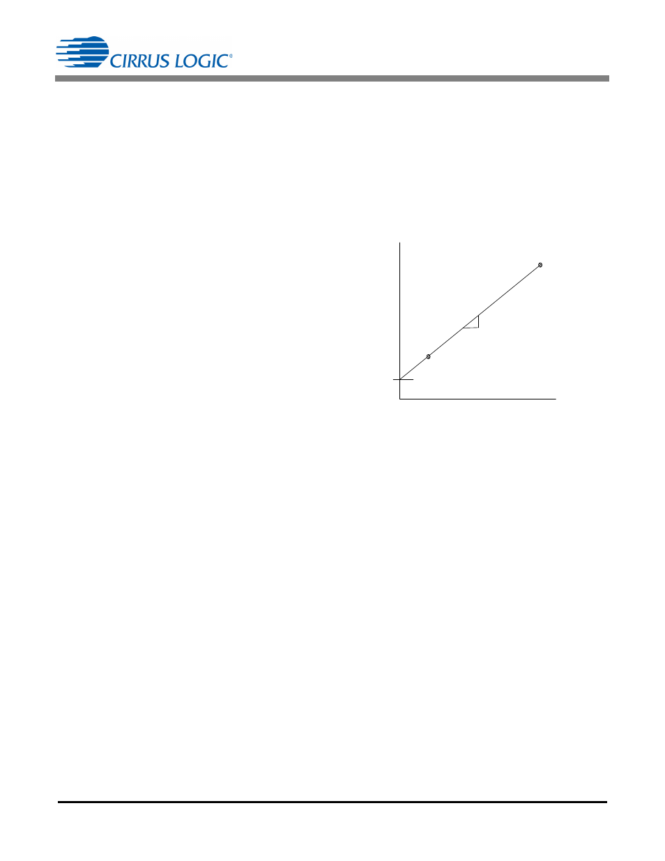
7.3.1 Temperature Offset and Gain Calibration
To obtain the optimal temperature offset (T
OFF
) register
value and temperature (T
GAIN
) register value, it is
necessary to measure the temperature (T) register at a
minimum of two points (T1 and T2) across the meter
operating temperature range. The two temperature
points must be far enough apart to yield reasonable
accuracy, for example 25
°
C and 85
°
C. Obtain a linear
fit of these points (
), where the slope (m)
and intercept (b) can be obtained.
Figure 20. T Register vs. Force Temp
T
OFF
and T
GAIN
are calculated using the equations
below:
y
m x b
+
=
F
or
ce T
e
m
p
er
at
ur
e (
°
C)
T Register Value
Y = m • x + b
m
b
T1
T2
TOFF
b
m
-----
=
TGAIN
m
=