1 pulse rate, Cs5490, Of 240v, and a maximum current (i – Cirrus Logic CS5490 User Manual
Page 20: And i
CS5490
20
DS982F3
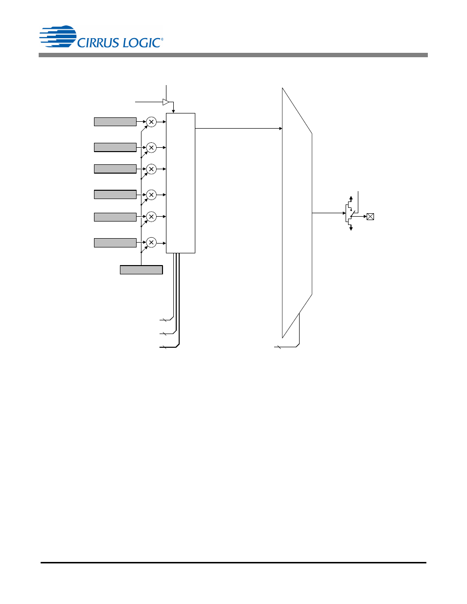
After reset, the energy pulse generation block is
disabled (DOMODE[3:0] = Hi-Z). To output a desired
energy pulse to a DO pin, it is necessary to follow the
steps below:
1. Write to register PulseWidth (page 0, address 8) to
select the energy pulse width and pulse frequency
range.
2. Write to register PulseRate (page 18, address 28) to
select the energy pulse rate.
3. Write to register PulseCtrl (page 0, address 9) to
select the input to the energy pulse generation block.
4. Write ‘1’ to bit EPG_ON of register Config1 (page 0,
address 1) to enable the energy pulse generation
block.
5. Wait at least 0.1s.
6. Write bits DOMODE[3:0] of register Config1 to select
DO to output pulses from the energy pulse
generation block.
7. Send DSP instruction (0xD5) to begin continuous
conversion.
5.5.1 Pulse Rate
Before configuring the PulseRate register, the full-scale
pulse rate needs to be calculated, and the frequency
range needs to be specified through FREQ_RNG[3:0]
bits in the PulseWidth register. For example, if a meter
has the meter constant of 1000imp/kWh, a maximum
voltage (U
MAX
) of 240V, and a maximum current (I
MAX
)
of 100A, the maximum pulse rate is:
[1000x(240x100/1000)]/3600 = 6.6667Hz.
Assume the meter is calibrated with U
MAX
and I
MAX
,
and the Scale register contains the default value of 0.6.
After gain calibration, the power register value will be
0.36, which represents 240 x 100 = 24kW or 6.6667Hz
pulse output rate. The full-scale pulse rate is:
F
out
= 6.6667/0.36 = 18.5185Hz.
Refer to section
6.6.6 Pulse Output Width (PulseWidth)
on page 36. The FREQ_RNG[3:0]
bits should be set to b[0110].
P
SUM
Sign
Q
SUM
Sign
P Sign
Q Sign
Reserved
V Crossing
I Crossing
DO_OD
(Config1)
(PulseCtrl) EPGIN[3:0]
DOMODE[3:0]
(Config1)
DO
Hi-Z
Interrupt
P
SUM
Q
SUM
S
SUM
P
AVG
Q
AVG
S
PULSE RATE
EPG_ON
(Config1)
MCLK
(PulseWidth) PW[7:0]
(PulseWidth) FREQ_RNG[3:0]
0000
0001
0010
0011
0100
0101
0110
0111
1000
E
n
e
rgy P
u
ls
e G
ene
ra
ti
on
(E
P
G
)
4
4
8
4
0000
0001
0010
0011
0100
0101
0110
0111
1000
1001
1010
1011
1100
1101
1110
1111
D
igi
ta
l O
u
tput
M
u
x
(D
O
)
Reserved
Reserved
Reserved
Reserved
Reserved
Reserved
Reserved
Reserved
Reserved
Figure 10. Energy Pulse Generation and Digital Output Control