Cs5490, 49 gain for voltage (v, Page 16, address 35 – Cirrus Logic CS5490 User Manual
Page 50: 50 average active power offset (p, Page 16, address 36, 51 average reactive power offset (q, Page 16, address 38, 52 ac offset for current (i, Page 16, address 37, 53 temperature gain (t
CS5490
50
DS982F3
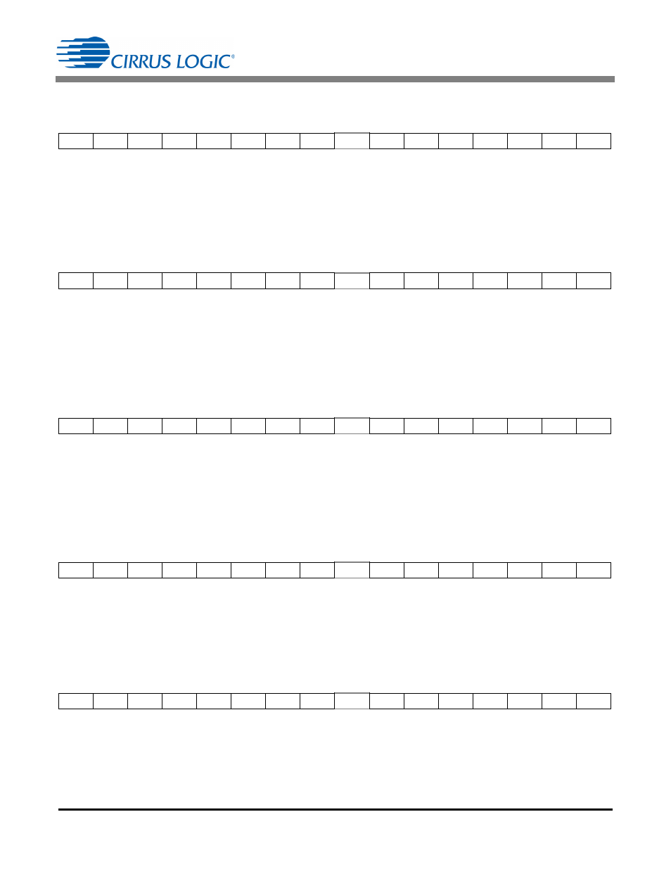
6.6.49 Gain for Voltage (V
GAIN
)
–
Page 16, Address 35
Default = 1.0
Gain register V
GAIN
is initialized to 1.0 on reset. During gain calibration, the V
GAIN
register is written with the
multiplicative inverse of the gain measured. This is an unsigned fixed-point value in the range of
0
value 4.0, with the binary point to the right of the second MSB.
6.6.50 Average Active Power Offset (P
OFF
)
–
Page 16, Address 36
Default = 0
Average Active Power Offset (P
OFF
) is added to the averaged active power to yield P
AVG
register results. It
can be used to reduce systematic energy errors. This is a two's complement value in the range of
-1.0
value 1.0, with the binary point to the right of the MSB.
6.6.51 Average Reactive Power Offset (Q
OFF
) – Page 16, Address 38
Default = 0x00 0000
Average Reactive Power Offset (Q
OFF
) is added to the averaged active power to yield Q
AVG
register results.
It can be used to reduce systematic energy errors. It is a two's complement value in the range of
-1.0
value 1.0, with the binary point to the right of the MSB.
6.6.52 AC Offset for Current (I
ACOFF
)
–
Page 16, Address 37
Default = 0
AC offset register I
ACOFF
is initialized to zero on reset. It is used to reduce systematic errors in the RMS re-
sults. This is an unsigned value in the range of 0
value 1.0, with the binary point to the left of the MSB.
6.6.53 Temperature Gain (T
GAIN
)
– Page 16, Address 54
Default = 0x 06 B716
Register T
GAIN
is used to scale the Temperature register (T), and is an unsigned fixed-point value in the range
of 0.0
value256.0, with the binary point to the right of bit 16.
Register T can be rescaled by the application using the T
GAIN
and T
OFF
registers. Refer to section
on page 54 for more information.
MSB
LSB
2
1
2
0
2
-1
2
-2
2
-3
2
-4
2
-5
2
-6
.....
2
-16
2
-17
2
-18
2
-19
2
-20
2
-21
2
-22
MSB
LSB
-(2
0
)
2
-1
2
-2
2
-3
2
-4
2
-5
2
-6
2
-7
.....
2
-17
2
-18
2
-19
2
-20
2
-21
2
-22
2
-23
MSB
LSB
-(2
0
)
2
-1
2
-2
2
-3
2
-4
2
-5
2
-6
2
-7
.....
2
-17
2
-18
2
-19
2
-20
2
-21
2
-22
2
-23
MSB
LSB
2
-1
2
-2
2
-3
2
-4
2
-5
2
-6
2
-7
2
-8
.....
2
-18
2
-19
2
-20
2
-21
2
-22
2
-23
2
-24
MSB
LSB
2
7
2
6
2
5
2
4
2
3
2
2
2
1
2
0
.....
2
-10
2
-11
2
-12
2
-13
2
-14
2
-15
2
-16