7 phase sequence detection, Cs5490 – Cirrus Logic CS5490 User Manual
Page 22
CS5490
22
DS982F3
5.7 Phase Sequence Detection
Polyphase meters using multiple CS5490 devices may
be configured to sense the succession of voltage
zero-crossings and determine which phase order is in
service. The phase sequence detection within CS5490
involves counting the number of OWR samples from a
starting point to the next voltage zero-crossing rising
edge or falling for each phase. By comparing the count
for each phase, the phase sequence can be easily
determined: the smallest count is first, and the largest
count is last.
The phase sequence detection and control (PSDC)
register provides the count control, zero-crossing
direction and count results. Writing '0' to bit DONE and
'10110' to bits CODE[4:0] of the PSDC register followed
by a falling edge on the RX pin will initiate the phase
sequence detection circuit. The RX pin must be held low
for a minimum of 500ns. When the device is in UART
mode, it is recommended that a 0xFF command be
written to all parts to start the phase sequence
detection. Multiple CS5490 devices in a polyphase
meter must receive the register writing and the RX
falling edge at the same time so that all CS5490 devices
starts to count simultaneously. Bit DIR of PSDC register
specifies the direction of the next zero crossing at which
the count stops. If bit DIR is '0', the count stops at the
next negative-to-positive zero crossing. If bit DIR is '1',
the count stops at the next positive-to-negative zero
crossing. When the count stops, the DONE bit will be
set by the CS5490, and then the count result of each
phase may be read from bits PSCNT[6:0] of the PSDC
register.
If the PSCNT[6:0] bits are equal to 0x00, 0x7F or
greater than 0x64 (for 50Hz) or 0x50 (for 60Hz), then a
measurement error has occurred, and the
measurement results should be disregarded. This could
happen when the voltage input signal amplitude is lower
than the amplitude specified in the VZX
LEVEL
register.
To determine the phase order, the PSCNT[6:0] bit
counts from each CS5490 are sorted in ascending
order.
and
illustrate how phase
sequence detection is performed.
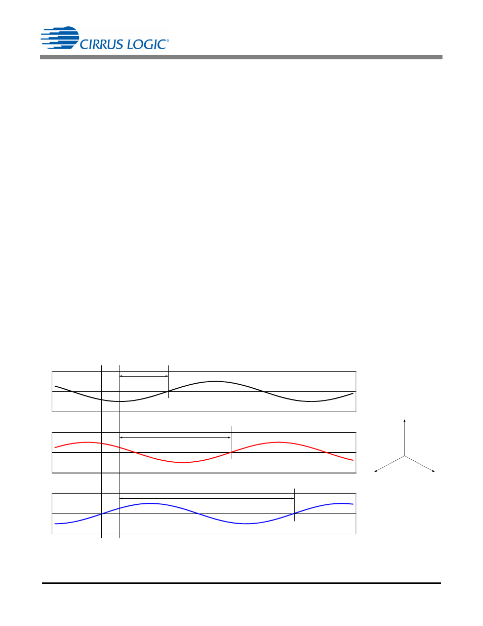
Phase sequences A, B, and C for the default rising edge
transition are illustrated in
. The PSCNT[6:0]
bits from the CS5490 on phase A will have the lowest
count, followed by the PSCNT[6:0] bits from the
CS5490 on phase B with the middle count, and the
PSCNT[6:0] bits from the CS5490 on phase C with the
highest count.
Phase sequences C, B, and A for rising edge transition
are illustrated in
. The PSCNT[6:0] bits from
the CS5490 on phase C will have the lowest count,
followed by the PSCNT[6:0] bits from the CS5490 on
phase B with the middle count, and the PSCNT[6:0] bits
from the CS5490 on phase A with the highest count.
Figure 12. Phase Sequence A, B, C for Rising Edge Transition
-2
0
2
Phase A Channel
-2
0
2
Phase B Channel
-2
0
2
Phase C Channel
Write 0x16 to
PSDC Register
Start on the Falling
Edge on the RX Pin
Stop
Stop
Stop
Phase C Count
Phase B Count
Phase A Count
A
B
C