System calibration, 1 calibration in general, Figure 19. calibration data flow – Cirrus Logic CS5490 User Manual
Page 52: 1 offset calibration, 1 dc offset calibration, 2 ac offset calibration, Cs5490
CS5490
52
DS982F3
7. SYSTEM CALIBRATION
Component tolerances, residual ADC offset, and
system noise require a meter that needs to be calibrated
before it meets a specific accuracy requirement. The
CS5490 provides an on-chip calibration algorithm to
operate the system calibration quickly and easily.
Benefiting from the excellent linearity and low noise
level of the CS5490, a CS5490 meter normally only
needs one calibration at a single load point to achieve
accurate measurements over the full load range.
7.1 Calibration in General
The CS5490 provides DC offset and gain calibration
that can be applied to the instantaneous voltage and
current measurements and AC offset calibration, which
can only be applied to the current RMS calculation.
Since the voltage and current channels have
independent offset and gain registers, offset and gain
calibration can be performed on any channel
independently.
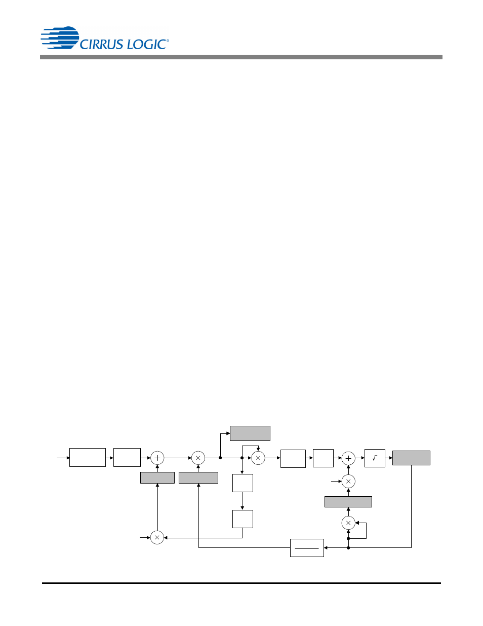
The data flow of the calibration is shown in
Note that in
the AC offset registers and gain
registers affect the output results differently than the DC
offset registers. The DC offset and gain values are
applied to the voltage/current signals early in the signal
path; the DC offset register and gain register values
affect all CS5490 results. This is not true for the AC
offset correction. The AC offset registers only affect the
results of the RMS current calculation.
The CS5490 must be operating in its active state and
ready to accept valid commands. Refer to section
on page 24 for different calibration
commands. The value in the SampleCount register
determines the number (N) of output word rate (OWR)
samples that are averaged during a calibration. The
calibration procedure takes the time of N + T
SETTLE
OWR samples. As N is increased, the calibration takes
more time, but the accuracy of the calibration results
tends to increase.
The DRDY bit in the Status0 register will be set at the
completion of calibration commands. If an overflow
occurs during calibration, other Status0 bits may be set
as well.
7.1.1 Offset Calibration
During offset calibrations, no line voltage or current
should be applied to the meter; the differential signal on
voltage inputs VIN± or current inputs IIN± of the CS5490
should be 0 volts.
7.1.1.1 DC Offset Calibration
The DC offset calibration command measures and
averages DC values read on specified voltage or
current channels at zero input and stores the inverse
result in the associated offset registers. This DC offset
will be added to instantaneous measurements in
subsequent conversions, removing the offset.
The gain register for the channel being calibrated
should be set to 1.0 prior to performing DC offset
calibration.
DC offset calibration is not required if the high-pass filter
is enabled on that channel because the DC component
will be removed by the high-pass filter.
7.1.1.2 AC Offset Calibration
The AC offset calibration applies only to the current
channel. It measures the residual RMS values on the
current channel at zero input and stores the squared
V
RMS
*
, I
RMS
*
Registers
IN
Modulator
Filter
N
* Denotes readable/writable register
Ϯ
Applies only to the current path (I1, I2)
N
N
-1
N
DC
RMS
-1
RMS
0.6(Scale
*
Ϯ
)
V
*
, I
*
, P
*
, Q
*
Registers
I
GAIN
*
, V
GAIN
*
Registers
I
DCOFF
*
, V
DCOFF
*
Registers
I
ACOFF
*
Ϯ
Register
Figure 19. Calibration Data Flow