7 digital interface formats, Figure 16. i²s format, Figure 17. left-justified format – Cirrus Logic CS42L52 User Manual
Page 35: Figure 18. right-justified format (dac only), 1 dsp mode
DS680F2
35
CS42L52
3/1/13
4.7
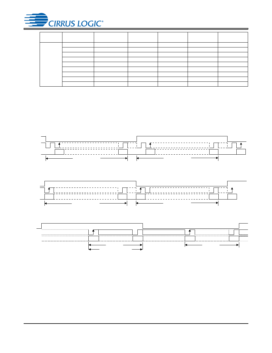
Digital Interface Formats
The serial port operates in standard I²S, Left-justified, Right-justified (DAC only), or DSP Mode digital inter-
face formats with varying bit depths from 16 to 24. Data is clocked out of the ADC or into the DAC on the
rising edge of SCLK.
4.7.1
DSP Mode
In DSP Mode, the LRCK acts as a frame sync for 2 data-packed words (left and right channel) input on
SDIN and output on SDOUT. The MSB is input/output on the first SCLK rising edge after the frame sync
rising edge. The right channel immediately follows the left channel.
27.0000
8.0000
11
1
1
01
0
12.0000
11
0
1
01
0
24.0000
10
0
1
01
0
32.0000
01
1
1
01
0
44.1176
01
0
1
11
0
48.0000
01
0
1
01
0
11.0294
11
0
1
11
0
22.0588
10
0
1
11
0
16.0000
10
1
1
01
0
MCLK
(MHz)
Sample Rate,
Fs (kHz)
SPEED[1:0]
(AUTO=’0’b)
32kGROUP
VIDEOCLK
RATIO[1:0]
MCLKDIV2
Table 1. MCLK, LRCK Quick Decode
LRCK
SCLK
M S B
L S B
M S B
L S B
AOUTA / AINxA
L e ft C h a n n e l
R ig h t C h a n n e l
SDOUT
SDIN
AOUTB / AINxB
MSB
Figure 16. I²S Format
LRCK
SCLK
M S B
L S B
M S B
L S B
L eft C h a n n e l
R ig h t C h a n n e l
SDOUT
SDIN
MSB
AOUTA / AINxA
AOUTB / AINxB
Figure 17. Left-Justified Format
LR C K
SC LK
M S B
L S B
M S B
L S B
L e f t C h a n n e l
R i g h t C h a n n e l
SD IN
AO U TL
A O U TR
Audio W ord Length (AW L)
Figure 18. Right-Justified Format (DAC only)