Figure 11. pwm output stage, Figure 12. analog output stage, 1 beep generator – Cirrus Logic CS42L52 User Manual
Page 29: Referenced control register location
DS680F2
29
CS42L52
3/1/13
4.3.1
Beep Generator
The Beep Generator generates audio frequencies across approximately two octave major scales. It offers
three modes of operation: Continuous, multiple, and single (one-shot) beeps. Sixteen on and eight off
times are available.
Note:
The Beep is generated before the limiter and may affect desired limiting performance. If the lim-
iter function is used, it may be required to set the beep volume sufficiently below the threshold to prevent
the peak detect from triggering. Since the master volume control, MSTxVOL[7:0], will affect the beep vol-
ume, DAC volume may alternatively be controlled using the PMIXxVOL[6:0] bits.
Referenced Control
Register Location
PWM Control
SPKxMUTE .........................
MUTE50/50 .........................
SPKMONO ..........................
SPKxVOL[7:0] .....................
SPKSWAP...........................
SPKB=A ..............................
BATTCMP ...........................
VPREF[3:0] .........................
VPLVL[7:0] ..........................
PDN_SPKx[1:0]...................
SPKxSHRT..........................
“Speaker Mute” on page 54
“Speaker Mute 50/50 Control” on page 54
“Speaker MONO Control” on page 54
“Speaker Volume Control” on page 64
“Speaker Channel Swap” on page 54
“Speaker Volume Setting B=A” on page 54
“Battery Compensation” on page 71
“VP Reference” on page 72
“VP Voltage Level (Read Only)” on page 72
“Speaker Power Control” on page 44
“Speaker Current Load Status (Read Only)” on page 72
Referenced Control
Register Location
Analog Output
HPxMUTE ...........................
HPxVOL[7:0] .......................
PDN_HPx[1:0] .....................
HPGAIN[2:0]........................
PASSTHRUx .......................
PASSxMUTE .......................
PASSxVOL[7:0] ...................
CHGFREQ ..........................
“Headphone Mute” on page 54
“Headphone Volume Control” on page 63
“Headphone Power Control” on page 44
“Headphone Analog Gain” on page 51
“Passthrough Analog” on page 52
“Passthrough Mute” on page 52
“Passthrough x Volume” on page 57
“Charge Pump Frequency” on page 73
Charge
Pump
DAC
CHGFREQ[3:0]
HPGAIN[2:0]
VOL
VOL
Analog Passthru
from PGA
HPAMUTE
HPBMUTE
HPA_VOL[7:0]
HPB_VOL[7:0]
+0dB/-102dB
0.5dB steps
PASSAMUTE
PASSBMUTE
PASSAVOL[7:0]
PASSBVOL[70]
+12dB/-60dB
0.5dB steps
(uses PGA)
PASSTHRUA
PASSTHRUB
PDN_HPA[1:0]
PDN_HPB[1:0]
A
B
from DSP
Engine
HP/Line
Outputs
VOL
PWM
Modulator
A
SPKAMUTE
SPKBMUTE
MUTE50/50
SPKMONO
SPKSWAP
SPKB=A
SPKAVOL[7:0]
SPKBVOL[7:0]
+0dB/-102dB
0.5dB steps
PDN_SPKA[1:0]
PDN_SPKB[1:0]
Short
Circuit
SPKASHRT
Battery
Compensation
BATTCMP
VPREF[3:0]
VPLVL[7:0]
SPKBSHRT
+
-
+
-
Gate
Drive
from DSP
Engine
Speaker
Outputs
B
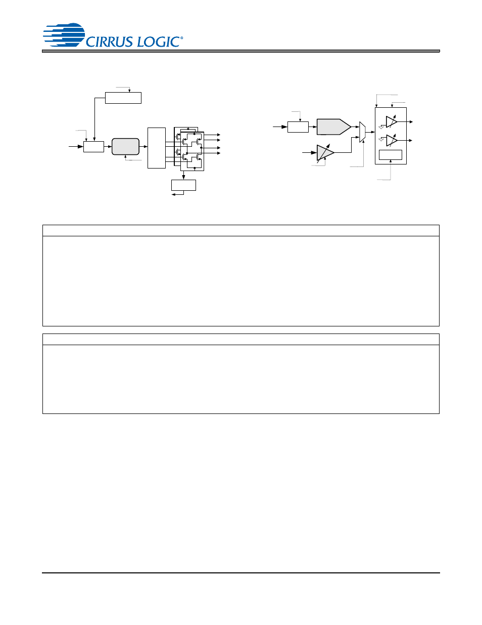
Figure 11. PWM Output Stage
Figure 12. Analog Output Stage