1 smps voltage conversion gain (k2), 2 amplifier gain path (k5), 4 smps (tps) modes – Cirrus Logic CS4234 User Manual
Page 77: Cs4234
DS899F1
77
CS4234
11.3.1
SMPS Voltage Conversion Gain (K2)
The gain of the SMPS voltage conversion, in units of V/V, can be determined by dividing the maximum
voltage of the SMPS by the maximum voltage permitted by the SMPS modulator stage. Preferably, the
maximum voltage permitted by the modulator will be equal to the full scale voltage of DAC5. If it is not,
the gain (or attenuation) of any circuitry between the outputs of DAC5 and the modulator must be taken
into account. For a differential SMPS, the maximum voltage is represented by VP+ - VP-. For single-end-
ed supplies, the maximum voltage is simply the largest single ended voltage that the SMPS can create.
11.3.2
Amplifier Gain Path (K5)
The amplifier gain is simply the gain applied to the output audio signal by the power amplifier. It is impor-
tant to note, however, that if different gain amplifiers are all connected to the SMPS, the highest gain set-
ting should be used to set the gain of the SMPS path.
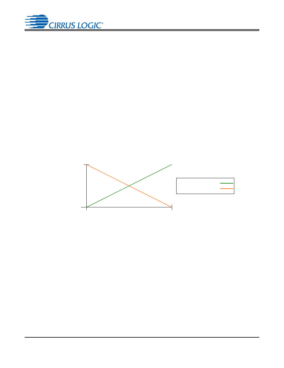
11.4 SMPS (TPS) Modes
The voltage output of a SMPS should be linear and will operate in one of two modes, depending on the to-
pology and modulation of the SMPS. In Mode 0, the SMPS output voltage will be directly proportional to the
control signal amplitude. In Mode 1, the SMPS output voltage will be inversely proportional to the control
signal amplitude. The transfer function for each mode, which details this behavior, is shown in
.
Because of these different modes of operation for the SMPS, it is necessary that the control signal be ref-
erenced to 0 V when the SMPS is operated in Mode 0 and referenced to the full scale output voltage of the
DAC when the SMPS is operated in Mode 1. To allow the control signal from DAC5 of the CS4234 to be
configured for both modes of operation, the
is provided. The
can be used to modify the control signal in mode 1.
shows both the single-ended and differential output signals for each mode of operation.
shows
how modifying the
and
controls affect the transfer functions in each
mode.
Min
SMPS
Control
Signal
SMPS
Rail
Voltage
Max
Min
Max
Directly Proportional (Mode 0):
Inversely Proportional (Mode 1):
Figure 48. Directly Proportional vs. Indirectly Proportional Modes of Operation