5 dac5 configuration and filter selection, 16 dac control 2 (address 13h), 1 dac5 noise gate – Cirrus Logic CS4234 User Manual
Page 63: 2 inv. dacx, 17 dac control 3 (address 14h), 1 dac5 attenuation, Cs4234
DS899F1
63
CS4234
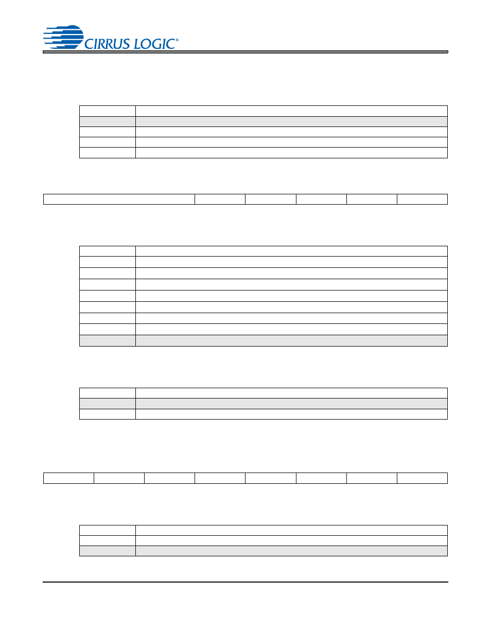
6.15.5
DAC5 Configuration and Filter Selection
Selects the filtering applied to the DAC5 data or configures the DAC5 Path used to generate a tracking
power supply reference. If placed into Tracking Power Supply mode, an interpolation filter is applied to
the outgoing data; otherwise, either an interpolation or a sample-and-hold filter can be applied to the path.
6.16 DAC Control 2 (Address 13h)
6.16.1
DAC5 Noise Gate
This sets the bit depth at which the Noise Gate feature should engage for the DAC5 path.
6.16.2
Inv. DACx
Inverts the polarity of the DACx signal.
When the DAC5 path is put into TPS mode, the invert bit for the DAC5 path will be inoperable.
6.17 DAC Control 3 (Address 14h)
6.17.1
DAC5 Attenuation
Sets the mode of attenuation used for the DAC5 path.
Note:
See
for details regarding the attenuation modes.
DAC5 FLTR
Filter Selected is:
00
Interpolation Filter
01
Sample and Hold
10
Tracking Power Supply Mode (See
for details)
11
Reserved
7
6
5
4
3
2
1
0
DAC5 NG[2:0]
INV. DAC5
INV. DAC4
INV. DAC3
INV. DAC2
INV. DAC1
DAC5 NG
Noise Gate is set at: [b]
000
Upper 13 Bits (72 dB)
001
Upper 14 Bits (78 dB)
010
Upper 15 Bits (84 dB)
011
Upper 16 Bits (90 dB)
100
Upper 17 Bits (96 dB)
101
Upper 18 Bits (102 dB)
110
Upper 24 Bits (138 dB)
111
Noise Gate Disabled
INV. DACx
DACx Polarity is:
0
Not Inverted
1
Inverted
7
6
5
4
3
2
1
0
DAC5 ATT
DAC1-4 ATT
MUTE LL
MUTE DAC5
MUTE DAC4
MUTE DAC3
MUTE DAC2
MUTE DAC1
DAC5 ATT
Attenuation events happen:
0
On a soft ramp
1
Immediately