Cirrus Logic CS4234 User Manual
Page 16
DS899F1
16
CS4234
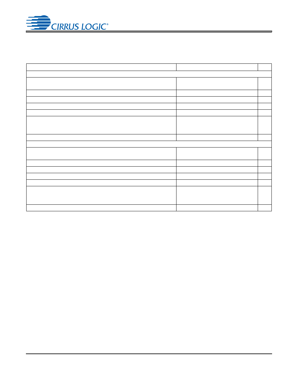
COMBINED DAC INTERPOLATION AND ON-CHIP ANALOG FILTER RESPONSE
Test Conditions (unless otherwise specified):
= 0 for VA = 3.3 VDC, 1 for VA = 5.0 VDC. The filter charac-
teristics have been normalized to the sample rate (F
S
) and can be referenced to the desired sample rate by multi-
plying the given characteristic by F
S
. See filter plots in
22. Response is clock dependent and will scale with F
S
.
23. For Single-Speed Mode, the measurement bandwidth is 0.5465 F
S
to 3 F
S
.
For Double-Speed Mode, the measurement bandwidth is 0.577 F
S
to 1.4 F
S
.
24. This specification is in addition to any delay added via the
“GROUP DELAY[3:0]” bits in the
.
25. The DAC group delay is measured from the FS/LRCK rising transition before the first bit of a group of
samples is transmitted on the SDINx pins to the time it appears on the AOUTx pins.
Parameter
Min
Typ
Max
Unit
Single-Speed Mode
Passband
to -0.05 dB corner
to -3 dB corner
0
0
-
-
0.4780
0.4996
F
S
F
S
Frequency Response 20 Hz to 20 kHz
-0.01
-
+0.12
dB
StopBand
0.5465
-
-
F
S
StopBand Attenuation
102
-
-
dB
DAC1-4 Group Delay
-
11/Fs
-
s
DAC5 Group Delay
(w/ interpolation filter)
(w/ sample and hold)
-
-
11/Fs
2/Fs
-
-
s
s
Low-Latency Group Delay
-
2/Fs
-
s
Double-Speed Mode
Passband
to -0.1 dB corner
to -3 dB corner
0
0
-
-
0.4650
0.4982
F
S
F
S
Frequency Response 20 Hz to 20 kHz
-0.05
-
+0.2
dB
StopBand
0.5770
-
-
F
S
StopBand Attenuation
80
-
-
dB
DAC1-4 Group Delay
-
7/Fs
-
s
DAC5 Group Delay
(w/ interpolation filter)
(w/ sample and hold)
-
-
7/Fs
2.5/Fs
-
-
s
s
Low-latency Group Delay
-
2.5/Fs
-
s