5 serial port interface, 1 tdm mode, Figure 14. tdm system clock format – Cirrus Logic CS4234 User Manual
Page 28: Cs4234
DS899F1
28
CS4234
The serial bit clock, SCLK, must be synchronously derived from the master clock, MCLK, and be equal to
512x, 256x, 128x, 64x, 48x or 32x F
S
, depending on the desired format and speed mode. Refer to
and
for required clock ratios.
Note:
35. For all cases, the SCLK frequency must be less than or equal to the MCLK frequency.
4.5
Serial Port Interface
The serial port interface format is selected by the
register bits. The TDM format is avail-
able in Slave Mode only.
4.5.1
TDM Mode
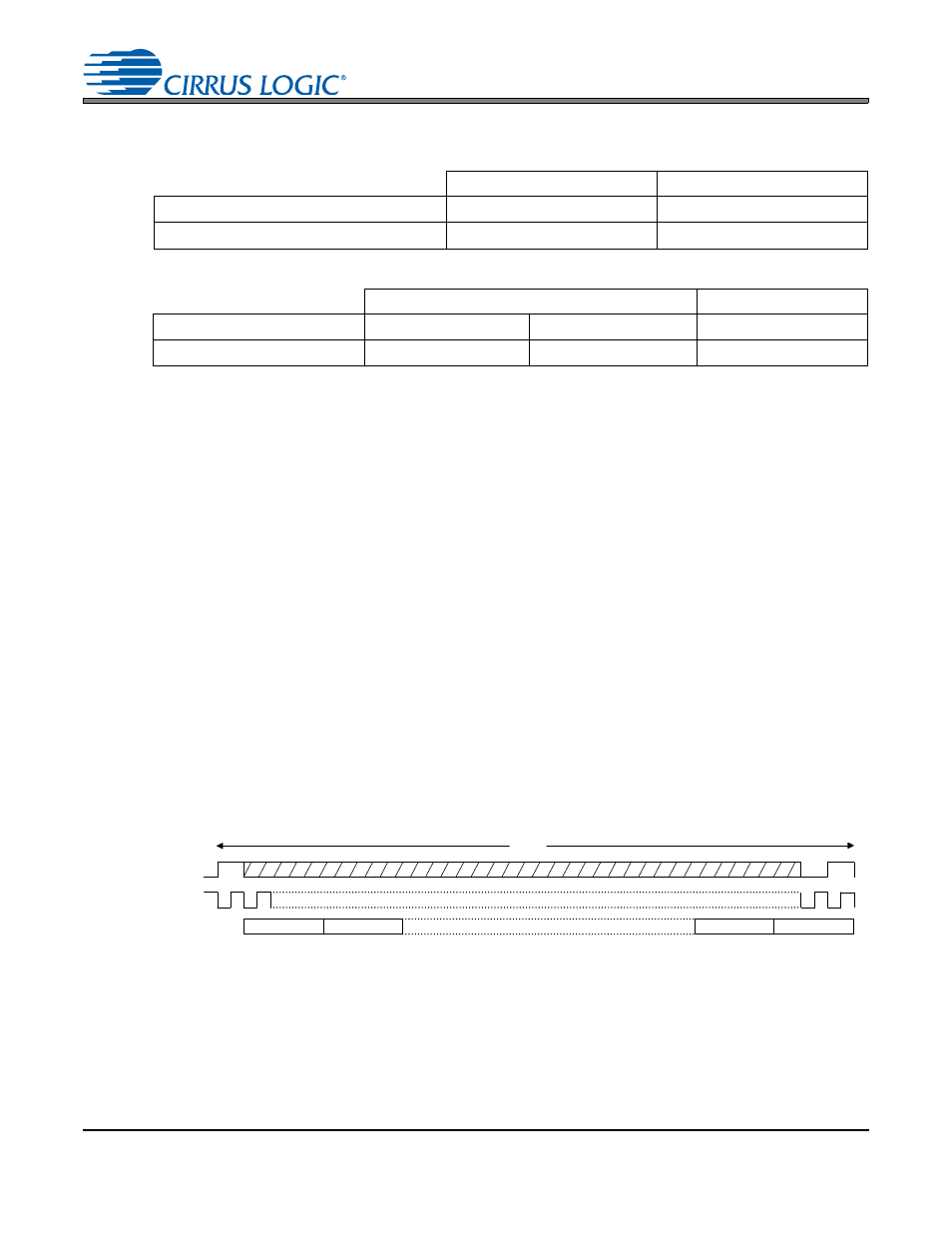
The serial port of the CS4234 supports the TDM interface format with varying bit depths from 16 to 24 as
shown in
. Data is clocked out of the ADC on the falling edge of SCLK and clocked into the DAC
on the rising edge.
As indicated in
, TDM data is received most significant bit (MSB) first, on the second rising edge
of the SCLK occurring after a FS/LRCK rising edge. All data is valid on the rising edge of SCLK. All bits
are transmitted on the falling edge of SCLK. Each slot is 32 bits wide, with the valid data sample left jus-
tified within the slot. Valid data lengths are 16, 18, 20, or 24 bits.
FS/LRCK identifies the start of a new frame and is equal to the sample rate, F
S
,
FS/LRCK is sampled as valid on the rising SCLK edge preceding the most significant bit of the first data
sample and must be held valid for at least 1 SCLK period.
SSM
DSM
MCLK/F
S
256x, 384x, 512x
128x, 192x, 256x
SCLK/F
S
32x, 48x, 64x, 128x
32x, 48x, 64x
Table 4. Slave Mode Left Justified and I²S Clock Ratios
SSM
DSM
MCLK/F
S
256x, 384x, 512x
512x
256x
SCLK/F
S
256x
512x
256x
Table 5. Slave Mode TDM Clock Ratios
SCLK
SDINx & SDOUT
Channel 1
Channel 2
Channel N-1
Channel N
FS
Frame
(N ≤ 16)
Figure 14. TDM System Clock Format