5 dac5 path, Figure 27. dac5 path, Cs4234 – Cirrus Logic CS4234 User Manual
Page 41: The 5
DS899F1
41
CS4234
4.6.5
DAC5 Path
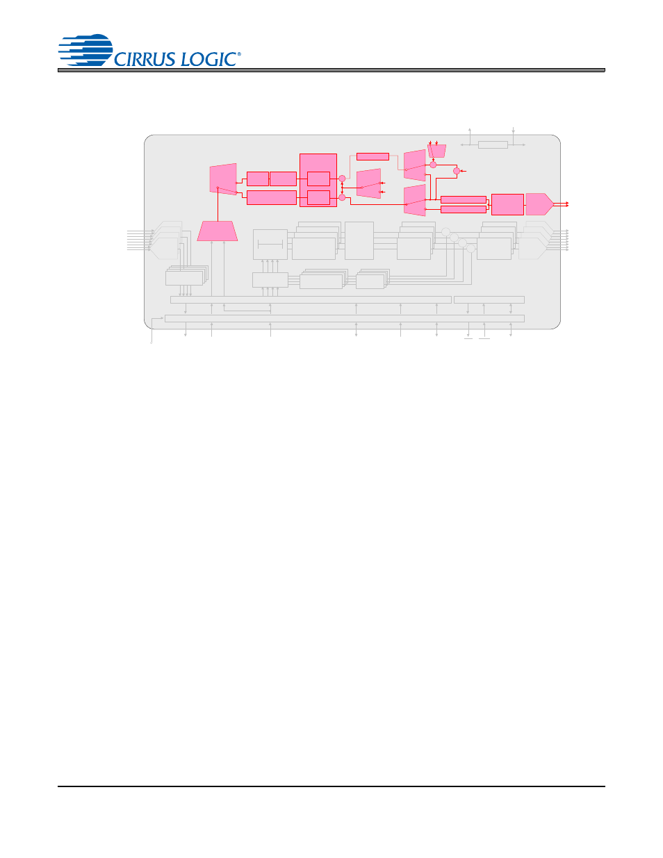
The 5
th
DAC in the CS4234 is a fully functional audio-grade DAC with performance specifications identical
to that of the other four DACs. In addition to the standard feature set, such as independent channel vol-
ume and muting, the 5
th
DAC can also be used to create a reference signal for an off-chip tracking power
supply. This functionality allows any Class AB amplifier to be operated as a Class H amplifier.
Within the DAC5 path, there are several routing options, primarily based upon which parts of the tracking
signal (if any) will be generated within the CS4234 or in an external DSP.
4.6.5.1
Generating the Tracking Signal Inside the CS4234
To generate the tracking signal internally, up to 32 channels of data present in the two TDM streams on
SDIN1 and SDIN2 can be considered. The max detect block determines the largest data sample on a
sample by sample basis. It then holds that sample for a period of time equal to that set in the group delay
block, effectively tracking the envelope of that calculated signal.
Set the
“DAC5 CFG & FLTR[1:0]” bits in the
to ‘10’ to select that the tracking
signal is to be generated within the CS4234. To include a channel of data in the calculation, unmask its
respective bit in the SDINx MASKx register. When the Tracking SMPS Enable bit is set, the signal can
not be inverted using the INV DAC5 bit.
In order to compensate for the difference between the gain of the Class AB amplifier stage and the gain
of the switch-mode power supply that generates the rails for the Class AB amplifier, the internal volume
block in the DAC5 path can be adjusted by changing the
.
Voltage is customarily added to the rails of a Class H amplifier to prevent clipping events from occurring
during high amplitude transients. This DC offset is accomplished within the CS4234 via the
.
Appendix A: Internal Tracking Power Supply Signal
for more detailed information about the internal
tracking signal.
Gain / Volume
Interpolation
Filter
Channel Volume ,
Mute, Invert,
Noise Gate
Multi-bit
Modulators
AOUT1 (±)
AOUT2 (±)
AOUT3 (±)
AOUT4 (±)
I
2
C Control
Data
Control Port
Level Translator
VL
1.8 to 5.0 VDC
RST
INT
SDIN1
SDOUTx
Group
Delay
0-500uS
Master Clock In
Frame Sync
Clock / LRCK
SDIN 2
Serial Clock
In / Out
LDO
Analog Supply
2.5 V
VA
5.0 VDC
VD
2. 5 VDC
Low -Latency
Demux
5
th
DAC
Input Advisory
DAC &
Analog
Filters
Tracking
SMPS
Enable
Sample
& Hold
Mute, Invert,
Noise Gate
Master
Volume
Control
Serial Audio Interface
AOUT 5 (±)
(SMPS Control )
DAC &
Analog
Filters
Master
Vol . Cntrl
Select
Master Volume
0 dB
TPS
GAIN
Filter
Select
X
Interpolation Filter
Sample & Hold
Max
Detect
Envelope
Tracking
Mute, Invert,
Noise Gate
DAC
Volume
Multi-bit
Modulators
Mode
Select
Full Scale Code
X
DC Offset
AIN4 (±)
AIN3 (±)
AIN2 (±)
AIN1 (±)
Digital Filters
Multi-bit
ADC
-2
X
Gain
S elect
-1
Figure 27. DAC5 Path