Figure 29, Cs4234, 1 mute behavior – Cirrus Logic CS4234 User Manual
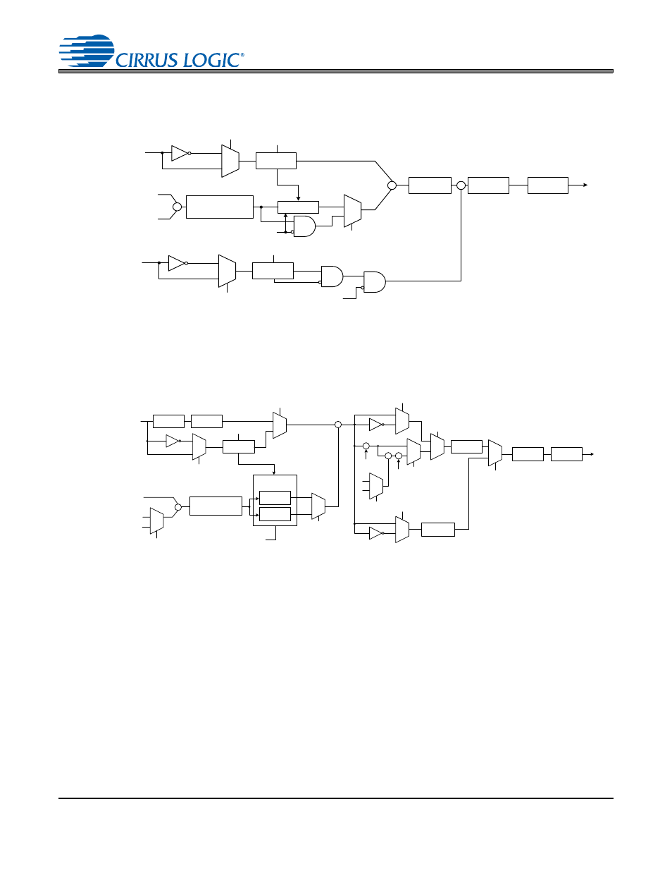
Page 43: Figure 29. volume implementation for the dac5 path
DS899F1
43
CS4234
control and other associated peripheries for DAC1-4 is shown in
tails for the volume control and other associated peripheries for the DAC5 path is shown in
4.6.6.1
Mute Behavior
Each DAC channel volume is controlled by the sum (in dB) of the individual channel volume and the mas-
ter volume registers (except for DAC5 if the
bit is cleared). The channel and master volume
control registers have a range of +6 dB to -90 dB with a nominal resolution of
6.02
/
16
dB per each bit, which
is approximately 0.4 dB. For DAC1-4, the sum of the two volume settings is limited to a range of +6 dB to
-90 dB. For DAC5, the sum of the two volume settings is limited to a range of +6 dB to -83 dB. Any volume
setting below these ranges will result in infinite attenuation thus muting the channel.
A DAC channel or low latency path may alternatively be muted by using the mute register bits, power
down bits, or the Noise Gate feature. For any case when the mute engages (volume is less than minimum
limit, power down bit is set, mute bit is set, or Noise Gate is engaged), the CS4234 will mute the channel
immediately or soft-ramp the volume down at a rate specified by the
bits depending
on the settings of the
. This behavior
also applies when unmuting a channel. The low latency paths are always muted or unmuted immediately.
1
0
Noise Gate
Soft Ramp
0
1
x
DACx Data
+
DACx Volume
Register Setting
Master Volume
Register Setting
Interpolation
Filter
Modulator
DAC
Limiter
(+6 to -90 dB)
INV. DACx
DAC1-4 Noise
Gate Threshold
MUTE DACx
DAC1-4 ATT
AOUTx
+
Low -
Latency
Data
Noise Gate
1
0
LL Noise Gate
Threshold
INV. DACx
MUTE LL
Figure 28. Volume Implementation for the DAC1-4 and Low-latency Path
Mute & Volume
Transition
Noise Gate
1
0
0
1
+
DAC5 Volume
Register Setting
Master Volume
Register Setting
1
0
1
0
Envelope
Tracking
x
DAC5
Data in
Max Detect
0
1
0
1
Modulator
DAC
Soft Ramp
Immediate
Change
Limiter
(+6 to -83 dB)
0 dB
INV. DAC5
DAC5 MVC
DAC5 Noise
Gate Threshold
MUTE DAC5
DAC5 ATT
AOUT5
DAC5 FLTR[1]
DAC5 FLTR[0]
TPS
OFFSET
Interpolation
Filter
DAC5 FLTR[1]
0
1
-1
-2
Full
Scale
Code
TPS
GAIN
+
0
1
x
+
TPS
MODE
0
1
TPS
MODE
0
1
TPS
MODE
Sample and
Hold
Figure 29. Volume Implementation for the DAC5 Path