Figure 20, Cs4234, Dac1-4, dac5, and low-latency signal routing – Cirrus Logic CS4234 User Manual
Page 33
DS899F1
33
CS4234
4.6.1.2
DAC1-4, DAC5, and Low-latency Signal Routing
In TDM mode, each of the 3 output paths have a collection of bits that advise the CS4234 where data for
each of the paths is located within the incoming TDM streams. For the DAC1-4 path, the bits are
. For the DAC5 path, the bits are the
. Finally, for the Low-Latency Path, the bits are the
. Details for these registers and the setting of their re-
spective bits can be found in
and
In Left Justified or I²S mode, the CS4234 routes the data on the SDIN1 pin to DAC1 and DAC2 and the
data on the SDIN2 pin to DAC3 and DAC4. DAC5 is unavailable in the PCM modes and should be placed
in the powered down state by using the appropriate
register bit. If it is powered up in
these modes, the DAC5 output will be active and may drive an AC or DC signal.
Device D
SDIN2
SDOUT1
SDIN1
x
x
Device A
SDIN2
SDOUT1
SDIN1
x
x
x
Device B
SDIN2
SDOUT1
SDIN1
x
x
x
Device C
SDIN2
SDOUT1
SDIN1
x
x
x
DSP
x
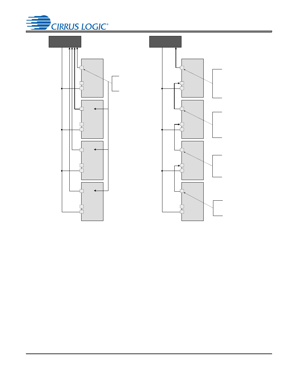
ADC data from Device A is loaded into the
first 4 slots of the 16 slot TDM Stream
going out of the SDOUT1 pin of Device A .
The last 12 slots are all coded as “ 0's”.
The ADC data of Device B is coded into the
first four slots of the output TDM stream,
followed by the first 12 slots of the TDM
stream coming in on SDIN2, placing the
ADC data from Device A into slots 5-8 of the
outgoing TDM stream.
The ADC data of Device C is coded into the
first four slots of the output TDM stream,
followed by the first 12 slots of the TDM
stream coming in on SDIN2, placing the
ADC data from Device B into slots 5-8 and
the ADC data from Device A into slots 9-12
of the outgoing TDM stream.
The ADC data of Device D is coded into the
first four slots of the output TDM stream,
followed by the first 12 slots of the TDM
stream coming in on SDIN2, placing the
ADC data from Device C into slots 5-8, the
ADC data from Device B into slots 9-12, and
the ADC data from Device A into slots 13-16
of the outgoing TDM stream.
Device D
SDIN2
SDOUT1
SDIN1
x
x
Device A
SDIN2
SDOUT1
SDIN1
x
x
x
Device B
SDIN2
SDOUT1
SDIN1
x
x
x
Device C
SDIN2
SDOUT1
SDIN1
x
x
x
DSP
x
Each of the device’s ADC data
is reflected in the TDM stream
on SDOUT1 and then routed to
the system controller.
Note:
This diagram shows the configuration for 16 slot TDM streams. If 8 slot TDM streams are used, two separate serial data lines will need to be
connected from the DSP. One would carry the serial data for Devices C&D and the other would carry the serial data for Devices A&B
Figure 20. Conventional SDOUT1 (Left) vs. Sidechain SDOUT1 (Right) Configuration