3 dac1-4 path, Figure 24. dac1-4 path, Cs4234 – Cirrus Logic CS4234 User Manual
Page 39: 1 de-emphasis filter
DS899F1
39
CS4234
4.6.3
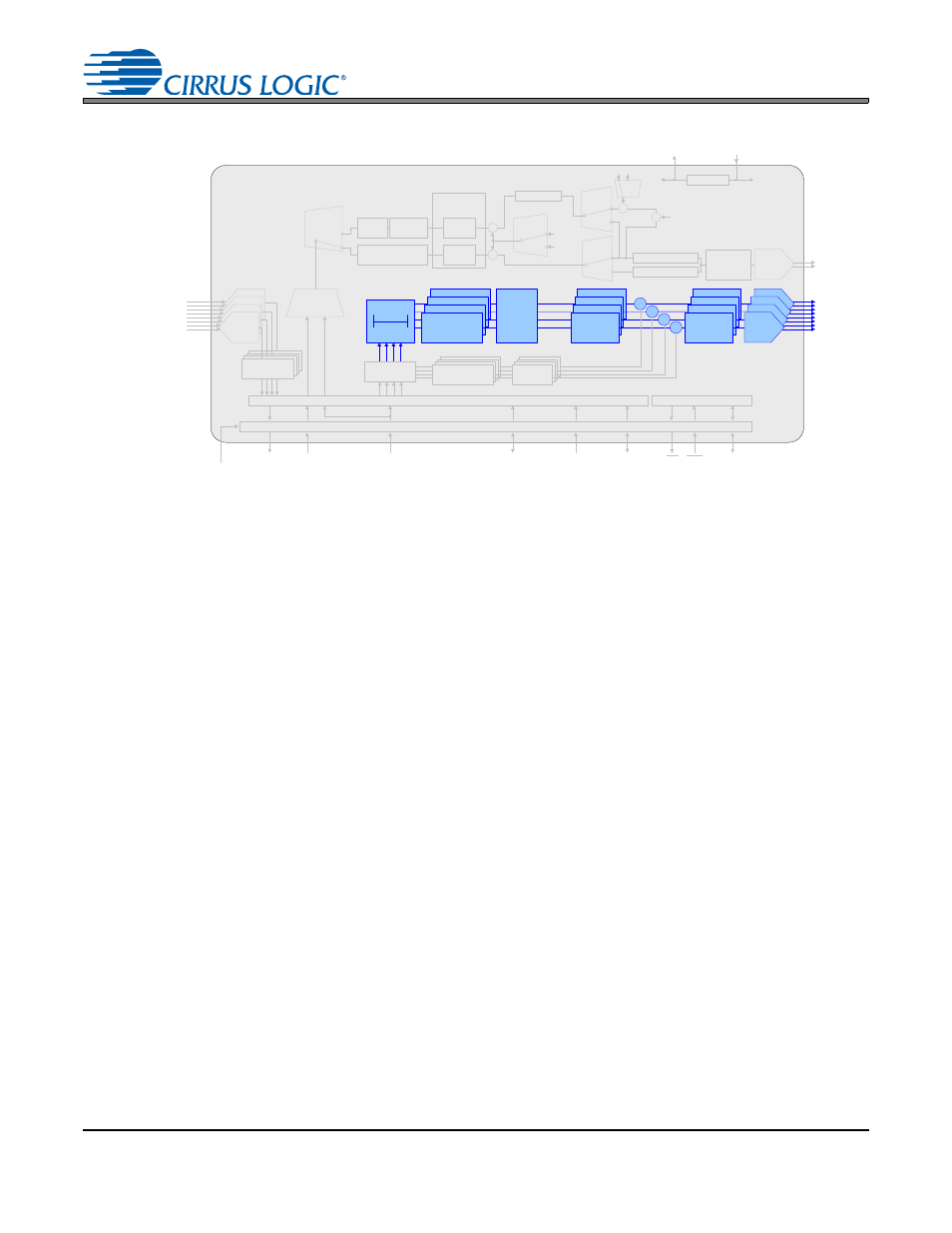
DAC1-4 Path
The AOUT1-4 signals are driven by the data placed into the DAC1-4 path. This data can be placed into
the DAC1-4 path via the
settings in the control port. These settings allow the input
source to be selected from any of the up to 32 slots of data on the incoming TDM streams on SDIN1 and
SDIN2.
The DAC1-4 path includes a programmable group delay which delays the output audio signals to allow
the DAC5 output to operate in feed-forward fashion, adjusting the voltage rails of the tracking power sup-
ply in anticipation of the coming audio signal. There is a connection between the group delay applied to
the audio signal and the ability of the SMPS to respond to high amplitude transients. By having a shorter
delay, the output voltage of the SMPS can track the audio signal more closely, increasing efficiency of the
Class H system. However, providing too short of a delay may prevent the SMPS to react fast enough to
high-amplitude transients, resulting in clipping of the output signal. For these reasons, the group delay of
the CS4234 can be adjusted from 100
s to 500 s, based on the settings of
bits. The group
delay should only be modified while all of the
and the
"DAC Control 4 (Address 15h)" register
are set to
‘1’b and the DAC outputs have entered the mute state (see
for mute ramp time when soft-ramp
is enabled). Note that the
“Base Rate Advisory” bits in the
"Clock and SP Select (Address 06h)" register
must be set to correctly calculate the selected group delay.
The DAC1-4 path also includes individual channel mutes. Separate volume controls are available for each
channel, along with a master volume control that simultaneously attenuates all four channels. The master
volume attenuation is added to any channel attenuation that is applied.
4.6.3.1
De-emphasis Filter
The CS4234 includes on-chip digital de-emphasis for 32, 44.1, and 48 kHz sample rates. It is not support-
ed for 96 kHz or for any settings in Double-speed Mode. The filter response is adjusted to be appropriate
for a particular base rate by the
bits. This filter response, shown in
, will vary
if these bits are not set appropriately for the given base rate. The frequency response of the de-emphasis
curve scales proportionally with changes in sample rate, F
S
. Please see
for de-emphasis control.
Gain / Volume
AIN4 (±)
AIN3 (±)
AIN2 (±)
AIN1 (±)
Interpolation
Filter
Channel Volume ,
Mute, Invert,
Noise Gate
Multi-bit
Modulators
AOUT1 (±)
AOUT2 (±)
AOUT3 (±)
AOUT4 (±)
I
2
C Control
Data
Control Port
Level Translator
VL
1.8 to 5.0 VDC
RST
INT
SDIN1
SDOUTx
Group
Delay
0-500uS
Master Clock In
Frame Sync
Clock / LRCK
SDIN 2
Serial Clock
In / Out
LDO
Analog Supply
2.5 V
VA
5.0 VDC
VD
2. 5 VDC
Low -Latency
Demux
5
th
DAC
Input Advisory
DAC &
Analog
Filters
Tracking
SMPS
Enable
Sample
& Hold
Mute, Invert,
Noise Gate
Master
Volume
Control
Serial Audio Interface
AOUT 5 (±)
(SMPS Control )
DAC &
Analog
Filters
Master
Vol . Cntrl
Select
Master Volume
0 dB
TPS
GAIN
Filter
Select
X
Interpolation Filter
Sample & Hold
Max
Detect
Envelope
Tracking
Mute, Invert,
Noise Gate
DAC
Volume
Multi-bit
Modulators
Mode
Select
Full Scale Code
X
DC Offset
Digital Filters
Multi-bit
ADC
-2
X
Gain
S elect
-1
Figure 24. DAC1-4 Path