Calulating specifications of reference system, Measuring system – Festo Контроллер двигателя SFC-ST User Manual
Page 90
A. Technical appendix
A−6
Festo P.BE−SFC−DC−PB−S7−E N en 0604NH
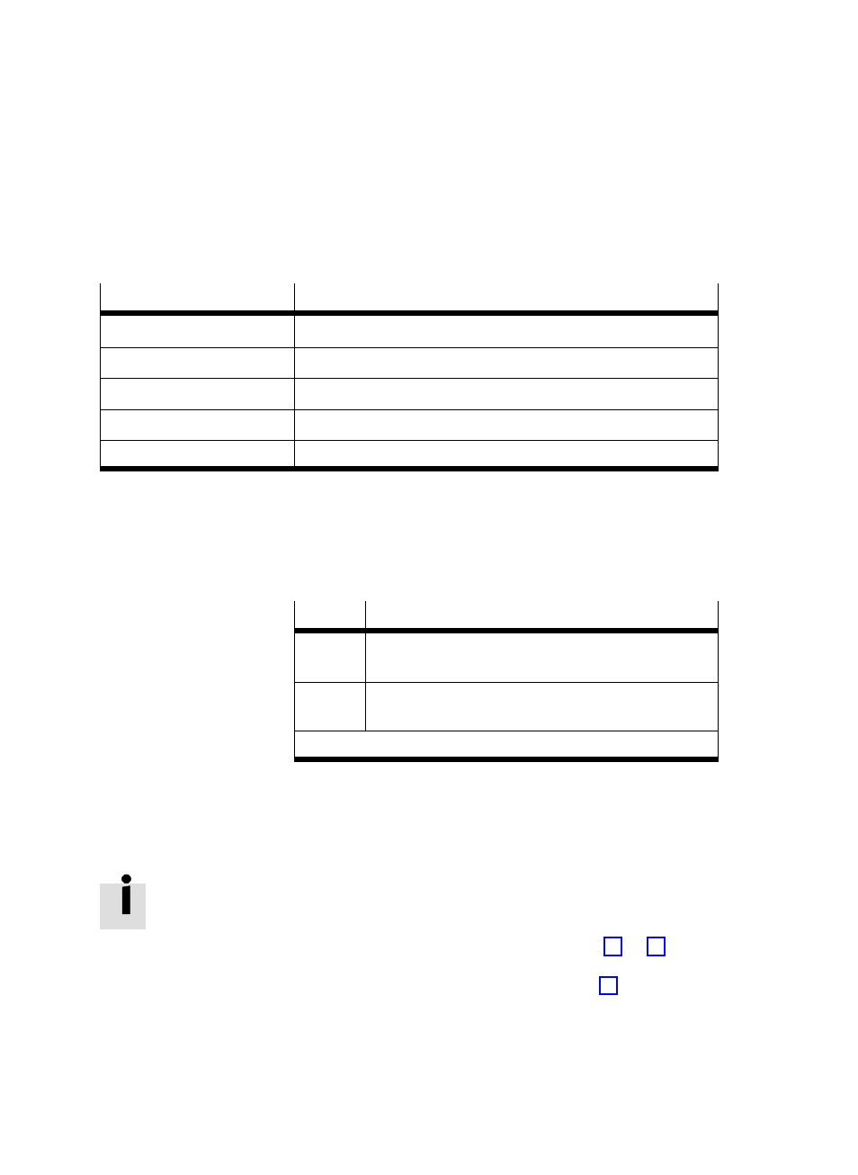
Calulating specifications of reference system
Reference point
Calculating specification
Axis zero point
AZ
= REF
+ a
Project zero point
PZ
= AZ
+ d
= REF
+ a + d
Lower software end position
LSE
= AZ
+ b
= REF
+ a + b
Upper software end position
USE
= AZ
+ c
= REF
+ a + c
Target/actual position
TP, AP
= PZ
+ e
= AZ
+ d + e
= REF
+ a + d + e
Tab. A/3:
Calulating specifications of reference system
All position values (offset, software end positions, target
positions...) have a mathematical sign and must be adapted
to the position of the relevant basis point.
Value
1)
Position values for SLTE−...
+
Positive values face from the basis point in the direction
away from the motor.
Ċ
Negative values face from the basis point in the
direction towards the motor.
1)
Factory setting (see PNU 1000)
Measuring system
All parameters are always saved internally in increments in
the SFC−DC (inc, inc/s, inc/s
2
...).
Positions transferred via the control block will be converted
with the aid of the position factor (see chapter 3.1.1, Tab. 3/1).
Measurements transferred via the parametrizing blocks alĆ
ways refer to an increment basis (see chapter 4.1.3).