Goulds Pumps 3600 - IOM User Manual
Page 82
Maintenance
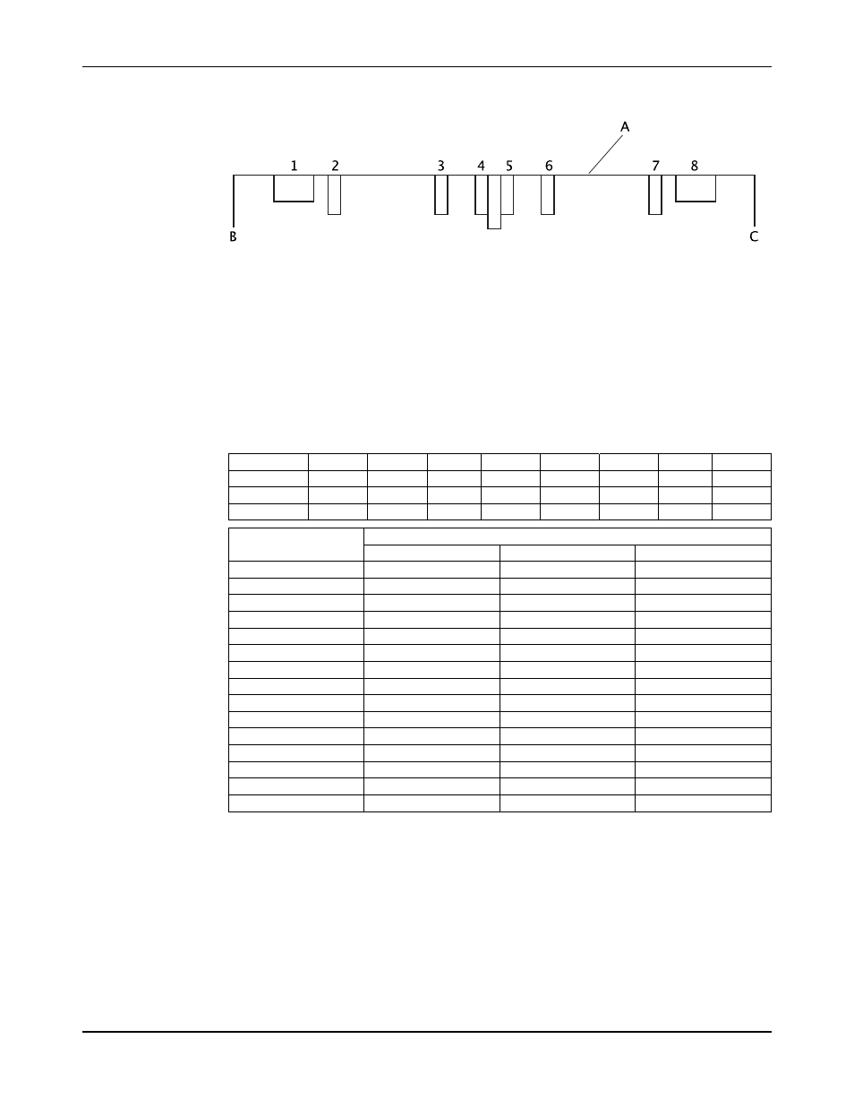
2. Measure the depth of the ring bores noted in the figure and record the measurements in the
table row "Actual depth."
1. Inboard seal chamber
2. Last ring bore
3. First ring, inboard side
4. Inboard center bushing bore
5. Outboard center bushing bore
6. Last ring, outboard side
7. First ring bore
8. Outboard seal chamber
A. Lower half casing flange
B. Inboard end
C. Outboard end
Location
1
2
3
4
5
6
7
8
Design depth
Actual depth
Difference
Design depth in inches
Pump size
1 and 8
7
2 through 6
3x4-8B
3.139
3.115
3.115
3x4-9
3.145
3.145
3.145
3x6-9/10
3.139
3.615
3.115
3x4-12.5
3.145
3.370
3.370
4x6-12
3.145
3.370
3.370
4x6-10
3.139
3.584
3.302
4x6-10D
3.139
3.302
3.302
4x6-11
3.139
3.552
3.990
4x6-11D
3.139
3.990
3.990
4x6-11A
3.145
3.995
3.995
6x8-11
3.145
4.427
4.427
6x8-13
3.745
4.745
4.745
6x8-14
3.145
4.620
4.620
8x10-13
3.145
4.870
4.870
10x12-14.5
3.342
5.275
5.275
3. For each bore, subtract the actual depth from the design depth and record the difference in
the table.
80
Model 3600, API 610 8th, 9th, 10th & 11th Editions (ISO 13709) Installation, Operation, and Maintenance Manual